FordParts
My Garage
My Account
Cart
OEM Ford E-150 Clock Spring
Spiral Cable Clock Spring- Select Vehicle by Model
- Select Vehicle by VIN
Select Vehicle by Model
orMake
Model
Year
Select Vehicle by VIN
For the most accurate results, select vehicle by your VIN (Vehicle Identification Number).
8 Clock Springs found


Ford E-150 Clockspring Part Number: AC2Z-14A664-C
$116.98 MSRP: $170.28You Save: $53.30 (32%)


Ford E-150 Clockspring Part Number: 4C2Z-14A664-BA
$98.81 MSRP: $143.83You Save: $45.02 (32%)Ships in 1-2 Business Days
Ford E-150 Clockspring Part Number: AC2Z-14A664-A
$118.86 MSRP: $182.92You Save: $64.06 (36%)


Ford E-150 Clockspring Part Number: 8C2Z-14A664-A
$92.04 MSRP: $133.97You Save: $41.93 (32%)Ships in 1-3 Business Days


Ford E-150 Clockspring Part Number: 4C2Z-14A664-AA
$94.66 MSRP: $137.78You Save: $43.12 (32%)Ships in 1 Business Day
Ford E-150 Clockspring Part Number: F8UZ-14A664-DA
$97.10 MSRP: $141.33You Save: $44.23 (32%)Ships in 1-2 Business Days

Ford E-150 Clockspring Part Number: 8C2Z-14A664-B
$97.28 MSRP: $141.60You Save: $44.32 (32%)Ships in 1 Business Day
Ford E-150 Clockspring Part Number: F7UZ-14A664-EC
$103.06 MSRP: $150.02You Save: $46.96 (32%)Ships in 1-3 Business Days
Ford E-150 Clock Spring
OEM Clock Spring boasts unmatched quality. Each part goes through full quality checks. They adhere to Ford's official factory standards. These steps remove flaws and inconsistencies. So you can get Clock Spring with long life and a perfect fit. Come to our website and find genuine Ford E-150 parts. We keep a wide inventory of OEM E-150 parts at the highly affordable prices. It's easy to search, compare, and pick what you need. You'll love the clear info and simple checkout. We offer top-rated customer service, and we reply fast. We also ship promptly to ensure your order arrives on time.
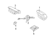
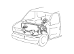
The Ford E-150 Clock Spring stands as a vital system component which provides critical electrical contacts between the airbag module and the electrical framework of Ford E-150 vehicles. Through its essential connection the deployment of airbags attains its deliberate effectiveness thus making collisions less dangerous for passengers. The Flat multicore spiral design of the Clock Spring enables it to store energy as the steering wheel rotates which makes the Ford E-150 perform effectively. Different Clock Spring versions have appeared across E-150 models throughout time as Ford worked to establish dependable products with maximum performance capability. The Clock Spring design uses two main configurations including spring-loaded brushes working with concentric slip rings and traditional spiral cable designs to match the various needs of E-150 production. The Ford E-150 Clock Spring functions with a wide range of model models thus providing versatility for maintaining safety and efficiency throughout the model series. The price range for clock spring replacement typically falls from $50 to $400 due to its vital role in vehicle operational functionality. The automotive market values the Clock Spring's unique features including its sturdy structure together with advanced engineering because these aspects enhance the automaker's legacy of creating reliable high-quality vehicles.
Ford E-150 Clock Spring Parts and Q&A
- Q: How to Service and Repair the Clock Spring Assembly on Ford E-150?A:The first step for repairing or servicing the Clock Spring requires safety glasses and proper handling of the air bag module to direct the trim cover away from your body. Prior to taking out the driver air bag module it is necessary to completely disable the system power. You must disconnect the electrical connector after you release all the retaining clips to remove steering column opening lower finish panel and its reinforcement before you remove the data link connector and bolts. Disengage the Clock Spring electrical connectors at the lower steering column base while maintaining the wheels in front-facing position before unfastening the Steering Wheel. When available twist off the tilt wheel handle and shank before taking out three screws which will be necessary for removing the lower steering column shroud. After positioning the Ignition Switch lock cylinder to RUN you should push upward on the cylinder release tab as you pull it outward to remove both the upper steering column shroud. Two strips of masking tape should be placed across the Clock Spring before you remove the key-in-ignition warning indicator switch and disconnect the electrical connector from the Clock Spring while separating the air bag electrical connector from the bracket. Remove the retaining clips from the Clock Spring then detach the wire from them before taking out the Clock Spring harness allowing it to pass through the instrument panel (04320). When installing you should remove the key while maintaining the rotor in a central position and keeping it from turning. To recenter the outer housing stays fixed while turning the rotor with clockwise motion until resistance appears and then countering the rotation for two and a quarter turns to achieve the center point. When reusing the Clock Spring remove the tape by hand without rotating it at any point. To bolt the Clock Spring onto the steering column you must correctly position the flats while sliding it forward. Seal it into place by applying force at six, twelve and three o'clock positions. The wiring should be secured into two clips while connecting the electrical connector of the Clock Spring and installing the pin-type retainer. To complete the installation process put in the key-in-ignition warning indicator switch before taking off the yellow anti-rotation tab when replacing the Clock Spring. Then put on the upper steering column shroud. After inserting the ignition switch lock cylinder into the steering column housing you should thoroughly check its operational performance throughout all positions. Place the lower steering column shroud along with the steering column opening cover and tilt wheel handle if present and the lower finish panel reinforcement at its installation position before securing it with bolts and attaching electrical connector pin-type retainers. First position the lower finish panel before installing the steering wheel while following all warning instructions. The last step involves connecting the horn and driver air bag module electrical connectors followed by driver air bag module installation into the steering wheel. Then install the two bolts along with back cover plugs before repowering the system.
- Q: What Precautions Should Be Taken When Servicing the Clock Spring Assembly on Ford E-150?A:Safety glasses are necessary for Clock Spring servicing because they protect against accidental air bag deployment while memory saver devices should be avoided. Any Ignition Switch activation with the RCM fuse removed backs up the warning light operation on the air bag control module but does not characterize an SRS system problem. Before giving the vehicle back to customers the SRS must operate without any problems. Repair procedures call for installing new parts but existing components need to be reinstalled if the issue continues and diagnostic steps should be done again. Start the process by disconnecting power from the system then taking out the driver air bag assembly. You must free retaining clips from the steering column opening lower finish panel to eliminate the pin-type retainer along with the electrical connector. The first step entails removing two screws and the data link connector then unfastening the six bolts holding the lower finish panel reinforcement. Start by disconnecting the Clock Spring electrical connectors from their placement at the steering column base before separating them from the supporting bracket. Straighten out the wheels of the road before dealing with the Steering Wheel removal process. Start by loosening the tilt wheel shank handle and afterwards remove the ignition switch lock cylinder by setting the ignition to RUN position and executing an upward tab push followed by pulling the cylinder outward. To access the inner column components start by unscrewing three hardware followed by removing both the lower and upper shrouds. Orientation tape must be applied to the center rotor to stop its rotation when a Clock Spring is reused. The key-in-ignition warning indicator switch can be removed if present along with the three Clock Spring retaining clips detachment for accessing the two clips securing the wire to the steering column before guiding the wiring through the instrument panel to extract the Clock Spring. A new Clock Spring installs with the help of a key seal which must be removed carefully to prevent rotor movement. To center an unaligned Clock Spring hold its outer housing steady while rotating the rotor first clockwise until resistance appears then counterclockwise for approximately 2.25 turns. Wash off tape from the Clock Spring without creating any rotation during the process. To properly mount the Clock Spring first position its rotor flats perpendicular to the steering column shaft before sliding it onto the column while pressing at 6 o'clock, 12 o'clock, and 3 o'clock to complete installation. The wiring should travel through the instrument panel while retaining clips get secured and key-in-ignition warning indicator switches will be installed (if your vehicle model has this feature). First put back the steering column shrouds both up and down then place the ignition switch lock cylinder at RUN position followed by complete column seating. Check the lock cylinder operation by rotating it and then continue with reinstalling the tilt wheel shank handle if present followed by the steering wheel. The connection of electrical connectors to the Clock Spring must be accomplished alongside pin-type retainer installation. The lower finish panel reinforcement needs to be installed using six bolts with the data link connector and electrical connector having its pin-type retainer attached. Reinstall the driver air bag module before you finish by seating the lower finish panel and powering up the system.


Related Ford E-150 Parts
 Ford E-150 Air Bag Control Module
 Ford E-150 Air Bag Sensor
 Ford E-150 Airbag
 Ford E-150 Battery Fuse
 Ford E-150 Brake Light Switch
 Ford E-150 Horn Relay
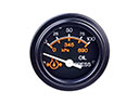 Ford E-150 Oil Pressure Gauge
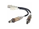 Ford E-150 Oxygen Sensor
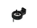 Ford E-150 Steering Angle Sensor
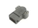 Ford E-150 Throttle Position Sensor
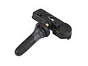 Ford E-150 TPMS Sensor
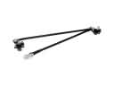 Ford E-150 Wiper Linkage