FordParts
My Garage
My Account
Cart
OEM Ford E-150 Air Bag Control Module
SRS Airbag Module- Select Vehicle by Model
- Select Vehicle by VIN
Select Vehicle by Model
orMake
Model
Year
Select Vehicle by VIN
For the most accurate results, select vehicle by your VIN (Vehicle Identification Number).
6 Air Bag Control Modules found


Ford E-150 Control Module Part Number: BC2Z-14B321-A
$544.11 MSRP: $806.08You Save: $261.97 (33%)Ships in 1-3 Business Days

Ford E-150 Control Module Part Number: 8C2Z-14B321-A
$503.01 MSRP: $738.63You Save: $235.62 (32%)Ford E-150 Control Module Part Number: KC2Z14B321A
$205.45 MSRP: $301.68You Save: $96.23 (32%)Ships in 1-2 Business Days
Ford E-150 Diagnostic Module Part Number: 6C2Z-14B321-BA
$387.59 MSRP: $569.15You Save: $181.56 (32%)Ships in 1-2 Business DaysFord E-150 Diagnostic Module Part Number: 6C2Z-14B321-AA
$392.50 MSRP: $542.99You Save: $150.49 (28%)Ships in 1-2 Business Days
Ford E-150 Control Module Part Number: F7UZ-14B056-AA
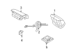
Ford E-150 Air Bag Control Module
OEM Air Bag Control Module boasts unmatched quality. Each part goes through full quality checks. They adhere to Ford's official factory standards. These steps remove flaws and inconsistencies. So you can get Air Bag Control Module with long life and a perfect fit. Come to our website and find genuine Ford E-150 parts. We keep a wide inventory of OEM E-150 parts at the highly affordable prices. It's easy to search, compare, and pick what you need. You'll love the clear info and simple checkout. We offer top-rated customer service, and we reply fast. We also ship promptly to ensure your order arrives on time.
Ford E-150 Air Bag Control Module Parts and Q&A
- Q: How to Service and Repair the Air Bag Control Module on Ford E-150?A:It is necessary to examine the RCM and impact sensor mounting areas after checking whether the vehicle underwent a crash. These areas require repair if they show signs of damage. New RCM units along with sensors need to be installed under all circumstances to stop fatal injuries. Handling the RCM at its mounting position with ignition ON should be avoided along with position changes because this action could activate the safety canopy unintentionally. To avoid system failure and shield electronic modules from static electricity perform the programmable module installation process called PMI when installing a new RCM. The air bag warning indicator will light up during ignition ON while the RCM fuse is removed which represents a normal condition not asociated with an SRS failure. All SRS functions must operate properly without faults before reinstating the vehicle to customers while new part installation should become the exclusive repair method. Start with removing the driver seat followed by attentive RCM cover removal through outward clip disengagement and sliding towards the back. Removing three fastener bolts on the RCM and bracket assembly requires disconnection of its large and small electrical connectors. The proper installation of RCM and impact sensor requires torquing the fasteners to 12 Nm (9 lb-ft) for normal function. Please establish complete release of the position assurance lever on the large connector before installing the small RCM electrical cable. Maintain the large connector in a straight position when installing to prevent harm and gently press the connector before using the lever for attachment. Reinstall both the RCM cover along with the driver seat followed by the PMI procedures. The SRS verification process requires turning the ignition from ON to OFF while waiting 10 seconds before returning it to ON position where the air bag indicator will activate for about 6 seconds before it turns OFF. A failure of SRS indicator to light up, combined with a 5 Hz indicator flash or 5 sets of 5 beeps from the chime requires SRS fault diagnosis and a scan tool for clearing all continuous DTCs from the RCM module.
- Q: What precautions should be taken when servicing the air bag control module and RCM on Ford E-150?A:Safety glasses should always be worn when servicing the air bag control module to prevent injuries from possible accidental deployment. A correct orientation of the restraints control module (RCM) ensures proper air bag deployment in any situation but checking the mounting and bracket for deformation becomes necessary after a collision damages the driver seat floor area. Replace the RCM immediately in such cases. The RCM installation area needs to maintain its original state and you should never employ memory saver devices to decrease personal injury threats. Start the process of disconnection or reconnection of RCM electrical connectors by depowering the SRS and securely anchoring the RCM along with its bracket to the floor pan to safeguard against damage. The RCM fuse removal with ON ignition turns on the air bag warning lamp but this illumination is normal and means no faults exist. The SRS component requires depowering during all seat-related servicing operations. Verification of the installed RCM together with functional SRS testing and absence of faults must be completed before returning the vehicle to its customer. Replace each faulty part with new components yet return the original part in case the problem persists beforehand conducting another diagnostic check. The processing sequence begins with depowering the system followed by removing the driver seat and prying from the sides to get rid of the RCM cover clips before pulling it backward. Cleared the large RCM electrical connector through lever disengagement beginning at the thumb tab followed by pivot positioning of the connector assurance lever backward while removing it from its socket. Detach the small RCM electrical connector before unfastening the three bolts securing both RCM and bracket assembly. The RCM bracket retaining bolts require a torque of 12 Nm (9 lb-ft) but inspection for any corrosion should happen first. Connect the small RCM electrical connector only after the large RCM connector position assurance lever is completely open and released to do so. When installing the large RCM electrical wiring connector avoid angling it to prevent bad connections and component damage since light pressure should be used before using the lever for full connector seating. To complete the process install the RCM cover while reinstalling the driver seat then power on the system.

Related Ford E-150 Parts
 Ford E-150 ABS Pump And Motor Assembly
 Ford E-150 Air Bag Sensor
 Ford E-150 Airbag
 Ford E-150 Clock Spring
 Ford E-150 Fuel Pump Relay
 Ford E-150 Ignition Relay
 Ford E-150 Intake Manifold Temperature Sensor
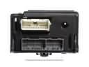 Ford E-150 Lighting Control Module
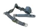 Ford E-150 Seat Belt
 Ford E-150 Temperature Sender
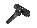 Ford E-150 TPMS Sensor
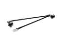 Ford E-150 Wiper Linkage