FordParts
My Garage
My Account
Cart
OEM Ford E-250 Air Bag Control Module
SRS Airbag Module- Select Vehicle by Model
- Select Vehicle by VIN
Select Vehicle by Model
orMake
Model
Year
Select Vehicle by VIN
For the most accurate results, select vehicle by your VIN (Vehicle Identification Number).
6 Air Bag Control Modules found


Ford E-250 Control Module Part Number: BC2Z-14B321-A
$544.11 MSRP: $806.08You Save: $261.97 (33%)Ships in 1-3 Business Days

Ford E-250 Control Module Part Number: 8C2Z-14B321-A
$503.01 MSRP: $738.63You Save: $235.62 (32%)Ford E-250 Control Module Part Number: KC2Z14B321A
$205.45 MSRP: $301.68You Save: $96.23 (32%)Ships in 1-2 Business Days
Ford E-250 Diagnostic Module Part Number: 6C2Z-14B321-BA
$387.59 MSRP: $569.15You Save: $181.56 (32%)Ships in 1-2 Business DaysFord E-250 Diagnostic Module Part Number: 6C2Z-14B321-AA
$392.50 MSRP: $542.99You Save: $150.49 (28%)Ships in 1-2 Business Days
Ford E-250 Control Module Part Number: F7UZ-14B056-AA
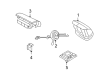
Ford E-250 Air Bag Control Module
OEM Air Bag Control Module boasts unmatched quality. Each part goes through full quality checks. They adhere to Ford's official factory standards. These steps remove flaws and inconsistencies. So you can get Air Bag Control Module with long life and a perfect fit. Come to our website and find genuine Ford E-250 parts. We keep a wide inventory of OEM E-250 parts at the highly affordable prices. It's easy to search, compare, and pick what you need. You'll love the clear info and simple checkout. We offer top-rated customer service, and we reply fast. We also ship promptly to ensure your order arrives on time.
The Ford E-250 Air Bag Control Module acts as an essential safety system component in the vehicle that boosts occupant protection during crashes. As a trusted and capable system the Air Bag Control Module in Ford E-250 models constantly watches sensor activities during crash events to activate airbags which protect occupants. The module functions to activate airbags and store essential crash data and diagnostic information which becomes necessary for post-accident inspections according to safety protocols. The Ford E-250 which belongs to the E-series family includes an Air Bag Control Module that is installed as standard equipment throughout the entire product range. The Air Bag Control Module's development has moved from large mechanical systems to contemporary electronic control units (ECUs) which deliver improved reliability with enhanced performance. The safety and technological development goals of Ford inspired this manufacturing advancement. The Air Bag Control Module demonstrates two main functions which enable it to handle various crash situations properly. The Automotive market recognizes the Ford E-250 Air Bag Control Module as its durable and technologically advanced safety component which sustains Ford vehicles through their safety and efficiency needs. The Air Bag Control Module represents an essential element of brand E-250's safety features because of its proven reliability which enhances the automaker's existing reputation for excellence.
Ford E-250 Air Bag Control Module Parts and Q&A
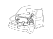
- Q: What precautions should be taken when servicing the air bag control module and RCM to ensure safety and proper operation on Ford E-250?A:Workers should wear safety glasses during air bag control module servicing steps to protect themselves from possible air bag deployments that could result in injury. Complete air bag functionality depends on the correct orientation of the restraints control module (RCM) while any damage in the driver seat floor area following a crash demands complete examination of mounting and bracket systems; an RCM replacement is mandatory even if air bags have not deployed. The area surrounding the RCM needs to be put back to its original state while memory saver devices should not be used because they increase personal injury risks. The RCM along with its bracket must be fastened to the floor pan and SRS depowering should happen before electrical connector handling to protect the RCM from static damage that affects electronic components. The air bag warning lamp will turn on when the RCM fuse is removed with the ignition switch ON yet this operation indicates no fault exists. Service a seat that has SRS components by power-down the SRS system while installing only the correct RCM to prevent reading incorrect DTCs. Returning a vehicle to the customer requires that the SRS operates properly with no detected faults. Repair procedures begin by installing new parts while you should return to the diagnostic process if the problem continues even with reinstallation of the original component. The procedure starts with system depowering before removing the driver seat and methodically unfastening the RCM cover through outward clipping while pushing it backward. Unplug the large RCM electrical connector through the tab pinch method followed by rotating the connector position assurance lever until you can easily remove the connector. The RCM assembly requires removal of its small electrical connector before extracting the bracket retaining bolts. The RCM bracket retaining bolts need 12 Nm (9 lb-ft) torque setting when installing them yet check for any corrosion first. Complete installation of the large RCM electrical connector by letting go the position assurance lever before linking the small RCM electrical connector. During installation do not angle the large RCM electrical wiring connector to stop bad connections and component damage then position the connector lightly before using the lever for complete seating. Conclusion of the procedure involves placing the RCM cover properly while repositioning the driver seat and restoring system power.
Related Ford E-250 Parts
 Ford E-250 Air Bag Sensor
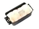 Ford E-250 Airbag
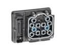 Ford E-250 Brake Controller
 Ford E-250 Clock Spring
 Ford E-250 Headlight Relay
 Ford E-250 Lighting Control Module
 Ford E-250 Oil Pressure Gauge
 Ford E-250 Spark Plug
 Ford E-250 Speedometer
 Ford E-250 Steering Angle Sensor
 Ford E-250 TPMS Sensor
 Ford E-250 Windshield Wiper Switch