FordParts
My Garage
My Account
Cart
OEM Ford Explorer Clock Spring
Spiral Cable Clock Spring- Select Vehicle by Model
- Select Vehicle by VIN
Select Vehicle by Model
orMake
Model
Year
Select Vehicle by VIN
For the most accurate results, select vehicle by your VIN (Vehicle Identification Number).
21 Clock Springs found


Ford Explorer Clockspring Part Number: GB5Z-14A664-F
$158.35 MSRP: $244.37You Save: $86.02 (36%)Ships in 1-2 Business Days


Ford Explorer Clockspring Part Number: 8L2Z-14A664-B
$181.35 MSRP: $263.97You Save: $82.62 (32%)


Ford Explorer Clockspring Part Number: GB5Z-14A664-D
$185.67 MSRP: $270.27You Save: $84.60 (32%)


Ford Explorer Clockspring Part Number: BA1Z-14A664-A
$185.67 MSRP: $270.27You Save: $84.60 (32%)Ships in 1-2 Business Days


Ford Explorer Clockspring Part Number: F87Z-14A664-BC
$229.92 MSRP: $337.62You Save: $107.70 (32%)


Ford Explorer Clockspring Part Number: GB5Z-14A664-C
$237.12 MSRP: $348.20You Save: $111.08 (32%)Ships in 1-2 Business Days


Ford Explorer Clockspring Part Number: F87Z-14A664-CC
$237.35 MSRP: $348.53You Save: $111.18 (32%)Ships in 1-3 Business Days
Ford Explorer Clockspring Part Number: GN1Z-14A664-D
$164.99 MSRP: $254.62You Save: $89.63 (36%)Ships in 1-2 Business DaysFord Explorer Clockspring Part Number: GN1Z-14A664-E
$215.65 MSRP: $316.67You Save: $101.02 (32%)Ships in 1-2 Business Days
Ford Explorer Cover And Contact Plate Assembly Part Number: RC5Z-14A664-B
$235.59 MSRP: $345.95You Save: $110.36 (32%)Ships in 1-2 Business Days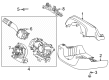
Ford Explorer Cover And Contact Plate Assembly Part Number: RC5Z-14A664-A
$235.59 MSRP: $345.95You Save: $110.36 (32%)Ships in 1-2 Business Days
Ford Explorer Clockspring Part Number: F87Z-14A664-EC
$387.08 MSRP: $535.49You Save: $148.41 (28%)Ships in 1-2 Business Days


Ford Explorer Clockspring Part Number: 5L5Z-14A664-A
$94.77 MSRP: $137.95You Save: $43.18 (32%)


Ford Explorer Clockspring Part Number: GB5Z-14A664-E
$181.73 MSRP: $264.53You Save: $82.80 (32%)


Ford Explorer Clockspring Part Number: 1L5Z-14A664-AB
$237.58 MSRP: $348.87You Save: $111.29 (32%)

Ford Explorer Clockspring Part Number: F87Z-14A664-DB


Ford Explorer Clockspring Part Number: 8L3Z-14A664-A


Ford Explorer Clockspring Part Number: 1L2Z-14A664-AB
Ford Explorer Clockspring Part Number: XL2Z-14A664-AA
Ford Explorer Clockspring Part Number: F67Z-14A664-EA
| Page 1 of 2 |Next >
1-20 of 21 Results
Ford Explorer Clock Spring
OEM Clock Spring boasts unmatched quality. Each part goes through full quality checks. They adhere to Ford's official factory standards. These steps remove flaws and inconsistencies. So you can get Clock Spring with long life and a perfect fit. Come to our website and find genuine Ford Explorer parts. We keep a wide inventory of OEM Explorer parts at the highly affordable prices. It's easy to search, compare, and pick what you need. You'll love the clear info and simple checkout. We offer top-rated customer service, and we reply fast. We also ship promptly to ensure your order arrives on time.
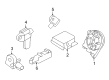
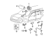
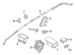
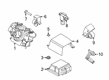
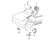
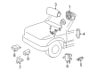
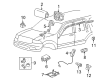
Supplemental Restraint System (SRS) in Ford Explorer depends upon the Clock Spring for delivering stable electrical links between the airbag module and vehicle's electrical framework. A functioning connection between airbag module and electrical system through the Clock Spring technology enables swift airbag deployment to protect passengers. The flat spiral structure of Clock Spring cables enables energy storage while steering wheel movement occurs thus making it an important safety element of Ford Explorer vehicles. Multiple versions of the Clock Spring design have appeared in Ford Explorer models to represent progress in security innovations alongside consumer needs regarding product dependability. Multiple Explorer models are supported by this design package which provides benefits of enhanced safety and efficiency across all generations of vehicles. Automotive buyers appreciate the Ford Explorer Clock Spring because of its durable design together with spring-loaded brushes that enhance electrical connection through concentric slip rings. The Ford car continues to develop and the Clock Spring serves as a crucial safety and reliability standard for all drivers who own this vehicle. The the automaker model Clock Spring has established itself as more than an automotive component since it plays a central role in keeping the car both efficient and safe.
Ford Explorer Clock Spring Parts and Q&A
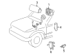
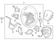
- Q: How is the Clock Spring Serviced and Repaired in an Air Bag Supplemental Restraint System (SRS) on Ford Explorer?A:Safety glasses should be worn before performing any work on an air bag supplemental restraint system (SRS) vehicle or handling the air bag module due to deployment risks which could cause bodily harm. Memory saver devices should always be avoided since they cannot help minimize personal injury situations. A normal condition exists when the air bag warning lamp illuminates as the RCM fuse gets removed and the Ignition Switch turns ON. The SRS must be completely operational after verification of its fault-free condition before giving the vehicle back to the customer. A new component needs to be installed during repairs but the issue should be reevaluated by returning to the original part and running another diagnosis test. Start the procedure by depowering the system and setting the road wheels in a forward position. To proceed with the repair start by taking out the driver air bag module and Steering Wheel along with the two screws from the steering column opening cover and then detach the cover from its base. Use gentle force to detach the gear selector boot leaving no markings then remove the three screws from the lower steering column shroud followed by removal of both the lower and upper steering column shrouds. When keeping the Clock Spring, apply two strips of masking tape but do it to stop accidental rotation during the removal process. Start by removing the multi-function switch screw after which you push the switch aside to access the two Clock Spring screws. The first step involves disconnecting electrical connectors from the Clock Spring followed by removing the component to check that the mounting bracket is free of damages. If any damage exists, discard the bracket after removing its three screws. Position the Clock Spring mounting bracket after removal and fasten it with three screws at 6 Nm (53 lb-in) torque followed by electrical connector connection. To properly center the Clock Spring maintain the outer housing immovable while rotating the rotor counterclockwise until you feel resistance and then proceed with clockwise rotation for about three turns while making sure the Clock Spring does not move from this central position. Insert the flats of the Clock Spring to the steering column before installing it along the column using two screws. New or used Clock Spring installation requires different procedures as removing the pin from a new Clock Spring but tape from a reused one. Begin installation by securing the multi-function switch with its screw before adding screws to the steering column shrouds starting from the upper and then the lower section. The system must be powered up after attaching the gear shift lever boot and installing lower steering column opening covers while reinstalling the driver air bag module and steering wheel.

Related Ford Explorer Parts
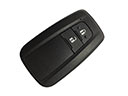 Ford Explorer Key Fob
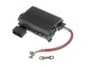 Ford Explorer Fuse Box
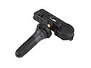 Ford Explorer TPMS Sensor
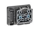 Ford Explorer Brake Controller
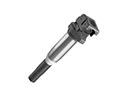 Ford Explorer Ignition Coil
 Ford Explorer Airbag
 Ford Explorer Antenna Mast
 Ford Explorer Antenna Base
 Ford Explorer Air Bag Control Module
 Ford Explorer Air Bag Sensor
 Ford Explorer Occupant Detection Sensor
 Ford Explorer PCV Valve Hose