FordParts
My Garage
My Account
Cart
OEM Ford Fusion Sway Bar Bushing
Stabilizer Sway Bar Bushing- Select Vehicle by Model
- Select Vehicle by VIN
Select Vehicle by Model
orMake
Model
Year
Select Vehicle by VIN
For the most accurate results, select vehicle by your VIN (Vehicle Identification Number).
15 Sway Bar Bushings found


Ford Fusion Stabilizer Bar Bushing, Rear Part Number: DG9Z-5493-G
$17.88 MSRP: $26.03You Save: $8.15 (32%)

Ford Fusion Stabilizer Bar Bushing, Front Part Number: DG9Z-5484-C
$18.14 MSRP: $26.40You Save: $8.26 (32%)Ships in 1-3 Business Days

Ford Fusion Stabilizer Bar Bushing, Front Part Number: DG9Z-5484-D
$23.14 MSRP: $32.82You Save: $9.68 (30%)


Ford Fusion Stabilizer Bar Bushing, Front Part Number: 6H6Z-5484-AA
$9.06 MSRP: $12.85You Save: $3.79 (30%)Ships in 1-3 Business Days

Ford Fusion Stabilizer Bar Bushing, Front Part Number: 7E5Z-5484-A
$9.31 MSRP: $13.20You Save: $3.89 (30%)Ships in 1-3 Business Days


Ford Fusion Stabilizer Bar Bushing, Rear Part Number: 6H6Z-5493-AA
$9.69 MSRP: $13.75You Save: $4.06 (30%)Ships in 1-3 Business Days
Ford Fusion Stabilizer Bar Bushing, Front Part Number: F2GZ-5484-B
$19.39 MSRP: $27.50You Save: $8.11 (30%)
Ford Fusion Stabilizer Bar Bushing, Rear Part Number: DP5Z-5493-C
$19.39 MSRP: $27.50You Save: $8.11 (30%)Ships in 1-3 Business Days
Ford Fusion Stabilizer Bar Bushing, Rear Part Number: DG9Z-5493-F
$23.15 MSRP: $32.83You Save: $9.68 (30%)
Ford Fusion Stabilizer Bar Bushing, Rear Part Number: F2GZ-5493-A
$20.42 MSRP: $28.97You Save: $8.55 (30%)Ships in 1-3 Business DaysFord Fusion Stabilizer Bar Bushing Part Number: HG9Z-5484-A
$22.75 MSRP: $32.27You Save: $9.52 (30%)Ships in 1-3 Business Days

Ford Fusion Stabilizer Bar Bushing, Rear Part Number: 7H6Z-5493-A


Ford Fusion Stabilizer Bar Bushing, Rear Part Number: 6E5Z-5493-AA
$6.69 MSRP: $9.48You Save: $2.79 (30%)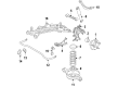
Ford Fusion Stabilizer Bar Bushing, Rear Part Number: 9E5Z-5493-B
Ford Fusion Stabilizer Bar Bushing, Rear Part Number: 7E5Z-5493-A
Ford Fusion Sway Bar Bushing
OEM Sway Bar Bushing boasts unmatched quality. Each part goes through full quality checks. They adhere to Ford's official factory standards. These steps remove flaws and inconsistencies. So you can get Sway Bar Bushing with long life and a perfect fit. Come to our website and find genuine Ford Fusion parts. We keep a wide inventory of OEM Fusion parts at the highly affordable prices. It's easy to search, compare, and pick what you need. You'll love the clear info and simple checkout. We offer top-rated customer service, and we reply fast. We also ship promptly to ensure your order arrives on time.
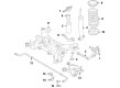
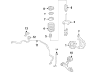
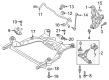
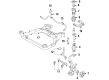
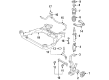
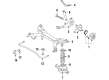
Sway Bar Bushing in Ford Fusion cars provides a firm linkage between the car's suspension system and the steering mechanism thereby improving the ride quality as well as stability of the automobile. These bushings are intended to absorb unequal surface irregularities and dampen loud and disturbing noises, and also to retain the sway bar that limits the car's body roll during the process of cornering. Generally, the Ford Fusion models contain the front and rear sway bar bushings that help in providing the car the correct balance it needs to handle well. In the course of time Ford Fusion Sway Bar Bushings may degrade level of responsiveness, produce rattle, squeak, and other similar problems. These symptoms may fester to worse steering and handling complication which may cause safety issues. Main objectives of Sway Bar Bushing include to regularly perform maintenance and lubrication so that it can be able to provide a smooth flow and stability in the vehicles to enable the drivers to ride in comfortably.
Ford Fusion Sway Bar Bushing Parts and Q&A
- Q: How to Service and Repair the Front Sway Bar Bushing in the Suspension on Ford Fusion?A:The first step for sway bar bushing front suspension maintenance requires users to set the Steering Wheel at straight-ahead and turn the ignition off. Detach the steering column shaft joint cover bolts at the bottom and pull out the cover assembly. The safety of the Clock Spring depends on a static steering column shaft because any shaft rotation during disconnection could damage the component. Such damage requires complete removal and centering of the clock spring. Establish an index on the steering column shaft for assembly reference before detaching it from the steering gear using the bolt while maintaining alignment of the marks during reinstall and pulling the bolt to 25 Nm torque (18 lb-ft). The steering column shaft-to-dash seal needs removal before installing the seal onto the steering gear correctly while ensuring all retaining clips are secured to avoid seal damage. To proceed, place the vehicle in neutral position on a hoist system before unscrewing eight mounting screws that allow you to set aside the LH and RH splash shields. Uninstall both splash shields by removing their six pin-type retainers, yet maintain 7 Nm (62 lb-in) torque when reinstalling the parts. Additionally, if an underbody cover shield is present, remove its bolts doing the same torque installation before reinstalling. Discard the old tie-rod end cotter pins and nuts and use fresh parts which should be torqued to 48 Nm (35 lb-ft) before installing newly placed cotter pins. A tie-rod end remover tool should be used to detach both wheel knuckle tie-rod ends with no hammer application, which would protect the components from damage. Discard the two Catalytic Converter-to-exhaust flexible pipe nuts and divide the exhaust flexible pipe before tightening new nuts to 40 Nm (30 lb-ft) torque setting. All-wheel drive vehicles require driveshaft-to-power transfer unit (PTU) indexing before bolt removal of the four units to set aside the driveshaft for reinstallation at 70 Nm (52 lb-ft). Begin by removing the RH steering gear-to-subframe bolt while making it 107 Nm (79 lb-ft) tight at reinstallation time. Then proceed to remove the two LH steering gear-to-subframe bolts before positioning the steering gear to reach the sway bar LH bracket front nut. Re-torque to 107 Nm (79 lb-ft) when reinstalling. Discard the four sway bar bracket nuts before uninstalling both sway bar brackets. Reinstall the new bracket nuts at 48 Nm (35 lb-ft). Before torquing sway bar bracket nuts, use a suitable jack to raise the suspension until the hub center sits 402 mm (15.83 in) from the fender lip. This will prevent clamp load-induced bushing damage. Perform the reverse of this removal method during installation.

Related Ford Fusion Parts
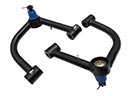 Ford Fusion Control Arm
 Ford Fusion Spindle
 Ford Fusion Axle Beam
 Ford Fusion Bump Stop
 Ford Fusion Camber and Alignment Kit
 Ford Fusion Control Arm Bolt
 Ford Fusion Control Arm Bracket
 Ford Fusion Steering Knuckle
 Ford Fusion Strut Housing
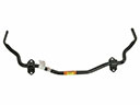 Ford Fusion Sway Bars
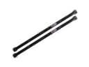 Ford Fusion Torsion Bar
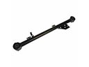 Ford Fusion Trailing Arm