FordParts
My Garage
My Account
Cart
OEM 2009 Ford Ranger Clock Spring
Spiral Cable Clock Spring- Select Vehicle by Model
- Select Vehicle by VIN
Select Vehicle by Model
orMake
Model
Year
Select Vehicle by VIN
For the most accurate results, select vehicle by your VIN (Vehicle Identification Number).
1 Clock Spring found


2009 Ford Ranger Clockspring Part Number: 9L5Z-14A664-A
$129.97 MSRP: $189.18You Save: $59.21 (32%)Product Specifications- Other Name: Cover And Contact Plate Assembly; Air Bag Clockspring
- Replaces: 7L5Z-14A664-A
- Base No.: 14A664
- Item Weight: 0.90 Pounds
- Item Dimensions: 9.1 x 8.4 x 3.0 inches
- Condition: New
- Fitment Type: Direct Replacement
- SKU: 9L5Z-14A664-A
- Warranty: This genuine part is guaranteed by Ford's factory warranty.
2009 Ford Ranger Clock Spring
If you're seeking quality and affordability, look no further than our extensive inventory of genuine 2009 Ford Ranger Clock Spring available at FordPartsDeal.com. You can confidently purchase our OEM 2009 Ford Ranger Clock Spring as they are supported by the manufacturer's warranty and our hassle-free return policy, alongside the benefit of our fast delivery service.
2009 Ford Ranger Clock Spring Parts Q&A
- Q: How to Service and Repair the Clock Spring Assembly on 2009 Ford Ranger?A: The first step for Clock Spring assembly servicing requires the Supplemental Restraint System (SRS) to be depowered before starting. When working with air bag modules keep the deployment door in an opposite direction from your body so unexpected deployments stay prevented. Controlling the air bag warning indicator requires the removal of the driver air bag module when using the appropriate Restraints Control Module (RCM) fuse during the ON ignition state. The steering wheel position needs to be straight ahead during the removal process of both the steering wheel and ignition lock cylinder. The hood release handle and steering column opening trim panel require two screws for removal and then the clips can be released for extraction of the lower steering column opening finish panel. First detach five bolts while removing the steering column opening cover reinforcement in addition to removing the tilt release lever/handle when equipment allows. The lower steering column shroud requires three screw removal before installing the upper shroud to gain access to the Clock Spring clips. Disconnect all wires from the Clock Spring before disconnecting the electrical connectors that include the wiring ground and releasing the lower Clock Spring clip. Before extricating the Clock Spring it is necessary to detach the screw and Passive Anti-Theft System (PATS) antenna and key-in-ignition warning indicator switch from the lock cylinder housing. During installation with new Clock Spring remove the key after positioning the rotor at center without rotation. In order to recenter the outer housing remains stationary while rotating the counterclockwise until resistance feels then rolling it clockwise to a desired 2.25 turns toward the center point. Install the PATS antenna and key-in-ignition warning indicator switch before installing the Clock Spring in the correct position along the steering column with tabs engagement. The electrical connectors plus ground wire need connection before upper and lower steering column shrouds receive position and secure installation along with the tilt release lever/handle and the steering column opening cover reinforcement which requires four bolts tightened at 8 Nm (71 lb-in). Position the wheels straight ahead as you put back the ignition lock cylinder and steering wheel and then install lower steering column trim and hood release handle. The procedure ends by reinstalling the driver air bag module while powering up the SRS system.
Related 2009 Ford Ranger Parts
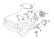
 2009 Ford Ranger Air Bag
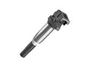 2009 Ford Ranger Ignition Coil
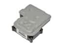 2009 Ford Ranger ABS Control Module
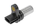 2009 Ford Ranger Camshaft Position Sensor
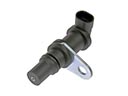 2009 Ford Ranger Crankshaft Position Sensor
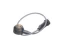 2009 Ford Ranger Knock Sensor
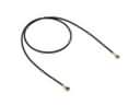 2009 Ford Ranger Speedometer Cable
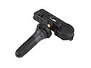 2009 Ford Ranger TPMS Sensor
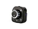 2009 Ford Ranger Mirror Switch
 2009 Ford Ranger Air Bag Control Module
 2009 Ford Ranger Air Bag Sensor
 2009 Ford Ranger Oxygen Sensors