FordParts
My Garage
My Account
Cart
OEM 2009 Lincoln Town Car Clock Spring
Spiral Cable Clock Spring- Select Vehicle by Model
- Select Vehicle by VIN
Select Vehicle by Model
orMake
Model
Year
Select Vehicle by VIN
For the most accurate results, select vehicle by your VIN (Vehicle Identification Number).
1 Clock Spring found


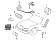
2009 Lincoln Town Car Clockspring Part Number: 6W1Z-14A664-A
$97.91 MSRP: $142.52You Save: $44.61 (32%)Product Specifications- Other Name: Cover And Contact Plate Assembly; Air Bag Clockspring
- Manufacturer Note: AFTER 05/23/06
- Replaces: 5W1Z-14A664-AA
- Base No.: 14A664
- Item Weight: 1.20 Pounds
- Item Dimensions: 8.1 x 6.0 x 3.0 inches
- Condition: New
- Fitment Type: Direct Replacement
- SKU: 6W1Z-14A664-A
- Warranty: This genuine part is guaranteed by Ford's factory warranty.
2009 Lincoln Town Car Clock Spring
If you're seeking quality and affordability, look no further than our extensive inventory of genuine 2009 Lincoln Town Car Clock Spring available at FordPartsDeal.com. You can confidently purchase our OEM 2009 Lincoln Town Car Clock Spring as they are supported by the manufacturer's warranty and our hassle-free return policy, alongside the benefit of our fast delivery service.
2009 Lincoln Town Car Clock Spring Parts Q&A
- Q: How to Ensure Proper Functioning of the Clock Spring on 2009 Lincoln Town Car?A: In order to repair a Clock Spring assembly, take out the steering wheel and put on masking tape to avoid turning. Take away the steering column shrouds, disconnect Clock Spring and move it off. To fit a new Clock Spring, center the rotor. Install the Clock Spring, shrouds and steering wheel and airbag module.
Related 2009 Lincoln Town Car Parts
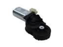 2009 Lincoln Town Car Seat Motor
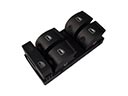 2009 Lincoln Town Car Window Switch
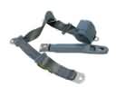 2009 Lincoln Town Car Seat Belt
 2009 Lincoln Town Car Air Bag
 2009 Lincoln Town Car Air Bag Control Module
 2009 Lincoln Town Car Air Bag Sensor
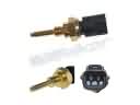 2009 Lincoln Town Car Cylinder Head Temperature Sensor
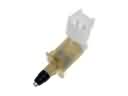 2009 Lincoln Town Car Door Jamb Switch
 2009 Lincoln Town Car Mass Air Flow Sensor
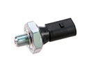 2009 Lincoln Town Car Oil Pressure Switch
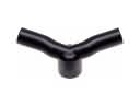 2009 Lincoln Town Car PCV Valve Hose
 2009 Lincoln Town Car Speedometer