FordParts
My Garage
My Account
Cart
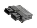
OEM Lincoln Air Bag Control Module
SRS Airbag Module- Select Vehicle by Model
- Select Vehicle by VIN
Select Vehicle by Model
orMake
Model
Year
Select Vehicle by VIN
For the most accurate results, select vehicle by your VIN (Vehicle Identification Number).
73 Air Bag Control Modules found


Lincoln Control Module Part Number: EA5Z-14B321-B
$455.17 MSRP: $713.65You Save: $258.48 (37%)Ships in 1-3 Business DaysProduct Specifications- Other Name: Sensor Assembly - Airbag; SDM Module; Sensor Assembly - Air Bag
- Replaces: DA5Z-14B321-B, EA5Z-14B321-A, DA5Z-14B321-C


Lincoln SDM Module Part Number: DP5Z-14B321-B
$503.49 MSRP: $789.42You Save: $285.93 (37%)Ships in 1-2 Business DaysProduct Specifications- Other Name: Sensor Assembly - Airbag; Diagnostic Unit; Sensor Assembly - Air Bag
- Manufacturer Note: RESTRAINT CONTROL MODULE
- Replaces: DP5Z-14B321-A


Lincoln Control Module Part Number: FL1Z-14B321-B
$108.48 MSRP: $166.95You Save: $58.47 (36%)Ships in 1 Business DayProduct Specifications- Other Name: Sensor Assembly - Airbag; Air Bag Control Module; SDM Module; Sensor Assembly - Air Bag
- Replaces: FL1Z-14B321-A


Lincoln SDM Module Part Number: H2GZ-14B321-B
$578.00 MSRP: $856.30You Save: $278.30 (33%)Ships in 1-3 Business DaysProduct Specifications- Other Name: Sensor Assembly - Airbag; Sensor Assembly - Air Bag
- Manufacturer Note: RESTRAINT CONTROL MODULE

Lincoln Passenger Discriminating Sensor Part Number: DE9Z-14B056-A
$811.65 MSRP: $1717.78You Save: $906.13 (53%)Ships in 1-2 Business DaysProduct Specifications- Other Name: Monitor - Airbag Diagnostic Module; Occupant Module
- Manufacturer Note: Occupant Classification System - ECU
- Position: Passenger Side


Lincoln Control Module Part Number: DT4Z-14B321-B
$526.43 MSRP: $835.60You Save: $309.17 (37%)Ships in 1-3 Business DaysProduct Specifications- Other Name: Sensor Assembly - Airbag; Air Bag Control Module; SDM Module; Sensor Assembly - Air Bag
- Replaces: DT4Z-14B321-A
Lincoln Control Module Part Number: AA5Z-14B321-B
$546.49 MSRP: $867.45You Save: $320.96 (37%)Ships in 1-3 Business DaysProduct Specifications- Other Name: Sensor Assembly - Airbag; SDM Module; Sensor Assembly - Air Bag
- Manufacturer Note: RESTRAINT CONTROL MODULE
- Replaces: AA5Z-14B321-A

Lincoln Control Module Part Number: CT4Z-14B321-A
$563.75 MSRP: $894.83You Save: $331.08 (37%)Ships in 1-3 Business DaysProduct Specifications- Other Name: Sensor Assembly - Airbag; SDM Module; Sensor Assembly - Air Bag

Lincoln Control Module Part Number: LL1Z-14B321-B
$353.89 MSRP: $519.67You Save: $165.78 (32%)Ships in 1-2 Business DaysProduct Specifications- Other Name: Sensor Assembly - Airbag; Air Bag Control Module; SDM Module

Lincoln Control Module Part Number: DE9Z-14B321-D
$388.07 MSRP: $608.45You Save: $220.38 (37%)Ships in 1-2 Business DaysProduct Specifications- Other Name: Sensor Assembly - Airbag; SDM Module
- Replaces: DE9Z-14B321-B, DE9Z-14B321-A
Lincoln SDM Module Part Number: HP5Z-14B321-E
$473.82 MSRP: $742.90You Save: $269.08 (37%)Ships in 1-3 Business DaysProduct Specifications- Other Name: Sensor Assembly - Airbag; Diagnostic Unit
- Manufacturer Note: RESTRAINT CONTROL MODULE
- Replaces: HP5Z-14B321-B, HP5Z-14B321-C, HP5Z-14B321-A, HP5Z-14B321-D
Lincoln Control Module Part Number: BL1Z-14B321-C
$134.78 MSRP: $208.00You Save: $73.22 (36%)Ships in 1-2 Business DaysProduct Specifications- Other Name: Sensor Assembly - Airbag; Air Bag Control Module; SDM Module; Sensor Assembly - Air Bag
- Replaces: BL1Z-14B321-A

Lincoln Control Module Part Number: F2GZ-14B321-C
$547.35 MSRP: $810.88You Save: $263.53 (33%)Ships in 1-3 Business DaysProduct Specifications- Other Name: Sensor Assembly - Airbag; SDM Module; Sensor Assembly - Air Bag
- Manufacturer Note: RESTRAINT CONTROL MODULE
- Replaces: F2GZ-14B321-B

Lincoln Control Module Part Number: HD9Z-14B321-C
$550.18 MSRP: $815.08You Save: $264.90 (33%)Ships in 1-3 Business DaysProduct Specifications- Other Name: Sensor Assembly - Airbag; SDM Module
- Replaces: HD9Z-14B321-AA, HD9Z-14B321-B, HD9Z-14B321-A

Lincoln Control Module Part Number: BT4Z-14B321-A
Product Specifications- Other Name: Sensor Assembly - Airbag; Air Bag Control Module; SDM Module; Sensor Assembly - Air Bag


Lincoln Control Module Part Number: BE9Z-14B321-A
Product Specifications- Other Name: Sensor Assembly - Airbag; SDM Module; Sensor Assembly - Air Bag
- Manufacturer Note: RESTRAINT CONTROL MODULE


Lincoln Diagnostic Unit Part Number: 9E5Z-14B321-C
Product Specifications- Other Name: Sensor Assembly - Airbag; Sensor Assembly - Air Bag
- Replaces: 8E5Z-14B321-B


Lincoln Control Module Part Number: 8L1Z-14B321-C
Product Specifications- Other Name: Sensor Assembly - Airbag; Air Bag Control Module; SDM Module; Sensor Assembly - Air Bag
- Replaces: 7L1Z-14B321-E, 7L1Z-14B321-D, 8L1Z-14B321-B, 8L1Z-14B321-A


Lincoln Diagnostic Module Part Number: 7E5Z-14B321-D
Product Specifications- Other Name: Sensor Assembly - Airbag; Air Bag Control Module; Diagnostic Unit; Sensor Assembly - Air Bag
- Replaces: 7E5Z-14B321-C


Lincoln Control Module Part Number: 5L3Z-14B321-AA
Product Specifications- Other Name: Sensor Assembly - Airbag; Air Bag Control Module; Diagnostic Module; Sensor Assembly - Air Bag
- Replaces: 4L3Z-14B321-AA
| Page 1 of 4 |Next >
1-20 of 73 Results
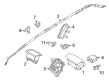
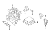
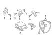
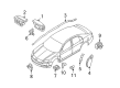
Lincoln Air Bag Control Module
If you own Lincoln and want to keep it in top shape, choosing OEM Air Bag Control Module is a smart move. They are precisely engineered and follow strict factory standards. They are made in advanced facilities that use cutting edge technology. Each part goes through thorough testing to confirm strength and safety, so you can trust it. FordPartsDeal.com gives you genuine Lincoln Air Bag Control Module at some of the affordable online prices without cutting quality. Every OEM Lincoln part includes the manufacturer's warranty, easy returns, and super-fast delivery. So why wait? Shop now and get your vehicle back to peak condition.
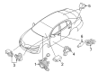
Lincoln Air Bag Control Module responds by blunt force and inflation of airbags in milliseconds. Lincoln goes in search of Quiet Flight to hush road rumble, dampen vibrations and ensure that drivers are at ease. Cabins are furnished with soft materials and clear screens in the brand, and Co-Pilot360 monitors lanes, blind spots and parking gaps. Lincoln also provides ActiveGlide such that the car can occupy the highway lane and cruise while your hands are relaxed. Feedback from owners goes directly to Lincoln and pressures annual tech changes that are made quietly. Cabin quiet is achieved due to generous sound deadening and active noise control silencing wind and tire noise. Comfortable seats and intelligent climate controls are to prevent tiredness during extensive road journeys. Air Bag Control Module is located at the center of the supplemental restraint system reading crash sensors at all times. Air Bag Control Module alone proves whether it is a mild or harsh hit and then it deploys the right airbags only. Air Bag Control Module captures the real-time impact data to be analyzed later to ensure that diagnostic tools confirm that all is working. Air Bag Control Module has been updated to use new propellants that cause nitrogens to spin rapidly and cut the remaining gases. This has been a gradual shift that keeps Lincoln abreast of the growing safety benchmarks in luxurious cars across the world.
Lincoln Air Bag Control Module Parts and Q&A
- Q: How to service the Air Bag Control Module safely and effectively on Lincoln Navigator?A:You should begin by depleting back up power before starting any work on the Air Bag Control Module to protect yourself from potential injury. The first step requires you to disconnect the battery ground cable followed by a one-minute wait period which encompasses the removal of all auxiliary batteries and power supplies. Electronic modules need protection from static electricity because they react negatively to electric charges. First secure the front seats in their maximum forward position and disconnect both screws which hold the trinket tray within the console. First remove the console insert placing it safely to the side before you take out all remaining screws located at the rear of the console on both sides. There are two pin-type fasteners on the left side and one on the right side of the instrument panel lower finish panel which needs to be removed after lifting the center console back as far as allowed by electrical connections. The procedure requires removal of the RCM screw positioned beneath the instrument panel center followed by disconnecting RCM electrical connectors before extracting the RCM from its location. When installing the RCM system operators need to follow the specified torque settings of its retaining bolts to maintain system functionality. Repeating the diagnostic method starts by reinstalling the original part and moving ahead with the new diagnostic round. The air bag system functionality needs to be verified after performing the installation by reversing the removal process. Before vehicle travel the restraint system diagnostic tool must be removed because it functions only for restraint system service while also ensuring compliance with vehicle safety standards.
- Q: How to service and repair the Air Bag Control Module on Lincoln Town Car?A:The first step when fixing an Air Bag Control Module starts with checking Restraints Control Module (RCM) along with impact sensor mounting areas for crash-related deformation; careful restoration of all damaged parts and new RCM and sensor installation is required because air bag deployment does not matter to stop serious injuries or fatalities. The RCM and impact sensor must always receive necessary torques according to specifications for their proper operation. After depowering the Supplemental Restraint System you can remove the carpet patch and ashtray through tab release and cigarette lighter disconnection and wire harness detachment. After removing the screws which secure the ashtray bracket the installer will find access to the RCM. Begin by removing the RCM insulator after which the RCM bolt fasteners on the right-hand side must be removed before separating both large and small RCM electrical connectors. Place the RCM into the required position then fasten the right-side bolts to 12 Nm (106 lb-in) before joining the small RCM electrical connector and screwing in the left-side bolt until it reaches 12 Nm (106 lb-in). Connect the connector position assurance lever reaches its full back position before connecting the large RCM electrical connector by aligning it correctly to prevent damage. Slightly push the connector during installation until you hear an audible click followed by securing it with the pivot connector position assurance lever. Install the insulator on the top of the RCM followed by torquing in the ashtray bracket screws and installing the ashtray with wire harness connected to the cigarette lighter To finish the procedure replace the carpet section followed by activating the SRS system power once again.