FordParts
My Garage
My Account
Cart
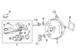
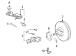
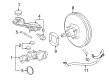
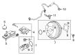
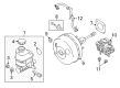
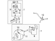
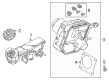
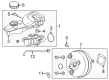
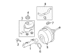
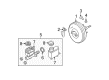
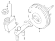
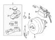
OEM Lincoln Brake Booster
Brake Power Booster- Select Vehicle by Model
- Select Vehicle by VIN
Select Vehicle by Model
orMake
Model
Year
Select Vehicle by VIN
For the most accurate results, select vehicle by your VIN (Vehicle Identification Number).
62 Brake Boosters found


Lincoln Brake Booster Part Number: F2GZ-2005-E
$143.65 MSRP: $236.36You Save: $92.71 (40%)Ships in 1-2 Business DaysProduct Specifications- Other Name: Booster Assembly - Brake; Power Brake Booster; Booster
- Replaces: BRB-130, BRB-147, F2GZ-2005-C, F2GZ-2005-A


Lincoln Brake Booster Part Number: AT4Z-2005-A
$180.68 MSRP: $300.00You Save: $119.32 (40%)Ships in 1-2 Business DaysProduct Specifications- Other Name: Booster Assembly - Brake; Power Brake Booster; Power Booster
- Replaces: 7T4Z-2005-A, 8T4Z-2005-A


Lincoln Brake Booster Part Number: BA1Z-2005-A
$183.96 MSRP: $305.45You Save: $121.49 (40%)Ships in 1 Business DayProduct Specifications- Other Name: Booster Assembly - Brake; Power Brake Booster; Power Booster


Lincoln Brake Booster Part Number: EJ7Z-2005-A
$192.72 MSRP: $320.00You Save: $127.28 (40%)Ships in 1-3 Business DaysProduct Specifications- Other Name: Booster Assembly - Brake; Power Booster


Lincoln Brake Booster Part Number: 5L1Z-2005-AA
$831.11 MSRP: $1380.00You Save: $548.89 (40%)Ships in 1-2 Business DaysProduct Specifications- Other Name: Booster Assembly - Brake


Lincoln Brake Booster Part Number: DL3Z-2005-D
$214.62 MSRP: $356.36You Save: $141.74 (40%)Product Specifications- Other Name: Booster Assembly - Brake; Power Brake Booster; Booster
- Replaces: AL1Z-2005-A, AL3Z-2005-A, BRB-96, BRB-40, DL3Z-2005-A


Lincoln Brake Booster Part Number: AE9Z-2005-A
$195.81 MSRP: $270.89You Save: $75.08 (28%)Ships in 1-2 Business DaysProduct Specifications- Other Name: Booster Assembly - Brake; Power Brake Booster; Power Booster
- Manufacturer Note: When Replacing This Component, 2L523 Has To Be Replaced

Lincoln Booster Assembly - Brake Part Number: PZ1Z-2005-K
$626.85 MSRP: $1085.45You Save: $458.60 (43%)Ships in 1-2 Business DaysProduct Specifications- Other Name: BOOSTER ASY - BRAKE
- Replaced by: PZ1Z-2005-M

Lincoln Brake Booster Part Number: G3GZ-2005-J
$214.21 MSRP: $364.00You Save: $149.79 (42%)Ships in 1-3 Business DaysProduct Specifications- Other Name: Booster Assembly - Brake; Power Booster
- Replaces: BRB-153, G3GZ-2005-C

Lincoln Brake Booster Part Number: DG9Z-2005-A
$198.03 MSRP: $332.00You Save: $133.97 (41%)Ships in 1-2 Business DaysProduct Specifications- Other Name: Booster Assembly - Brake; Power Brake Booster; Booster
Lincoln Brake Booster Part Number: GJ7Z-2005-B
$205.86 MSRP: $341.82You Save: $135.96 (40%)Ships in 1-3 Business DaysProduct Specifications- Other Name: Booster Assembly - Brake; Power Booster
Lincoln Brake Booster Part Number: GJ7Z-2005-C
$208.38 MSRP: $346.00You Save: $137.62 (40%)Ships in 1-3 Business DaysProduct Specifications- Other Name: Booster Assembly - Brake; Power Booster
- Replaces: BRB-166, GJ7Z-2005-A
Lincoln Brake Booster Part Number: HG9Z-2005-J
$214.40 MSRP: $356.00You Save: $141.60 (40%)Ships in 1-3 Business DaysProduct Specifications- Other Name: Booster Assembly - Brake; Power Brake Booster; Power Booster; Booster
- Replaces: BRB-158, HG9Z-2005-A

Lincoln Brake Booster Part Number: HG9Z-2005-F
$215.61 MSRP: $358.00You Save: $142.39 (40%)Ships in 1-3 Business DaysProduct Specifications- Other Name: Booster Assembly - Brake; Booster


Lincoln Brake Booster Part Number: AE5Z-2005-A
$150.00 MSRP: $238.18You Save: $88.18 (38%)Product Specifications- Other Name: Booster Assembly - Brake; Power Brake Booster; Power Booster; Booster


Lincoln Brake Booster Part Number: 9E5Z-2005-A
Product Specifications- Other Name: Booster Assembly - Brake; Power Brake Booster; Power Booster; Booster
- Manufacturer Note: When Replacing This Component, 2L523 Has To Be Replaced


Lincoln Brake Booster Part Number: 8L3Z-2005-B
Product Specifications- Other Name: Booster Assembly - Brake; Power Brake Booster; Booster Assembly
- Replaces: 6L3Z-2005-BB


Lincoln Brake Booster Part Number: 8L1Z-2005-B
Product Specifications- Other Name: Booster Assembly - Brake; Power Brake Booster; Booster Assembly; Booster
- Manufacturer Note: Service Part May Differ From Production
- Replaces: 7L1Z-2005-C, 8L1Z-2005-C


Lincoln Brake Booster Part Number: 5L3Z-2005-BA
Product Specifications- Other Name: Booster Assembly - Brake; Power Brake Booster; Booster Assembly
- Replaces: XL3Z-2005-CA


Lincoln Brake Booster Part Number: 3W1Z-2005-AA
Product Specifications- Other Name: Booster Assembly - Brake; Power Brake Booster; Power Booster
| Page 1 of 4 |Next >
1-20 of 62 Results
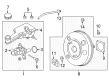
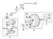
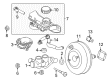
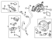
Lincoln Brake Booster
If you own Lincoln and want to keep it in top shape, choosing OEM Brake Booster is a smart move. They are precisely engineered and follow strict factory standards. They are made in advanced facilities that use cutting edge technology. Each part goes through thorough testing to confirm strength and safety, so you can trust it. FordPartsDeal.com gives you genuine Lincoln Brake Booster at some of the affordable online prices without cutting quality. Every OEM Lincoln part includes the manufacturer's warranty, easy returns, and super-fast delivery. So why wait? Shop now and get your vehicle back to peak condition.
Lincoln Brake Booster reduces the force applied on the pedal to make it easy to stop smoothly and confidently in traffic. Lincoln is a cabin lover and its Quiet Flight motto seals away the noise of the wind, modulates shaking and makes conversation painless. Lincoln layers touch-soft trims, broad digital screens and smart controls that react quickly, hence drivers peep and proceed. Lincoln packages Co-Pilot360 technologies such as lane assist, blind-spot notifications, auto high beams and parking assist which reduce stress levels. Owner feedback makes Lincoln updated and each model year has newer ideas, smoother rides and better driver aids. Cabins remain so quiet as to make conversation readily overcome by any playlist volume on rough asphalt highway drives. Long travels are made easy by the intuitive technology which takes responsibility for the routine duties and the suspension sweeps potholes before they can hit you. Brake Booster works based on engine vacuum to enhance the force that your foot applies to the hydraulic master cylinder. On vacuum units a sealed chamber is divided by a diaphragm; manifold suction causes the pressure on one side to be lower than on the other, atmosphere fills the other and your pedal operates the pushrod with additional bite. Alternatives of Brake Booster feed on steering-pump hydraulics, convenient when there is no consistent vacuum in the turbo engine. Soon failures of Brake Booster are mostly due to the rupture of the diaphragm, loss of vacuum or saturated seals hence hard pedals alert early. To achieve desired pedal feel, Brake Booster has single or two-diaphragm options and various diameters.
Lincoln Brake Booster Parts and Q&A
- Q: How to service the vacuum brake booster on Lincoln Navigator?A:The first step to service the vacuum brake booster requires disconnecting the ground cable of the battery. You should first loosen the clamp to split the air cleaner outlet tube and resonator from the air cleaner followed by removing the mass air flow (MAF) sensor electrical connector. Extract the air cleaner assembly from the air cleaner tray while you remove the three power steering reservoir screws and put the reservoir to one side before securing it to 11 Nm (8 ft. lbs.) when reinstalling. First detach the brake fluid level switch and afterward disconnect the brake pressure switch when present. Secure the master cylinder in place by using a mechanic wire or wire tie while you remove and dispose of both brake master cylinder nuts before setting the master cylinder aside with a torque of 22 Nm (16 ft. lbs.). The degas bottle requires removal of its bolts following which you can set the bottle aside while tightening the bolts to 9 Nm (80 inch lbs.). Disconnnect both electrical connectors for the pedal travel sensor and solenoid if they are installed on the system. The vacuum brake booster hose can be unhooked through release of the compression clamp. Completely disconnect the booster pushrod by first removing the cotter pin cover, pin, washer and bushing as well as switch. Check that the pushrod offset faces downward when reinstalling the components. The brake booster-to-pedal bracket nuts must be removed through sound insulation access after which the brake booster can be taken out while tightening to 25 Nm (18 foot lbs.) when reinstalling. Reverse the removal steps while using new nuts on the master cylinder installation.
- Q: How to service and repair the vacuum brake booster on Lincoln Town Car?A:Service and repair operations on the vacuum brake booster start with disconnecting the battery ground cable along with the fluid level sensor connector. Starting with bracket position of the speed control cable and next detach the power brake booster check valve. Begin services of the vacuum brake booster by unscrewing the brake master cylinder nuts before removing the wiring harness bracket followed by placing all components to the side. Take out the brake master cylinder after disconnecting it before setting it aside. The instrument close-out panel removal starts with pushpin removal and further requires the stoplight switch retaining pin to be taken out. Unfasten the brake pedal pin from the stoplight switch and booster push rod before removing the power brake booster retaining nuts to pull out the system. Edge the brake switch installation by placing the closed hole facing away from the brake pedal arm while positioning the open hole upward before proceeding with the removal process in reverse order.


Related Lincoln Parts
 Lincoln Brake Pads
 Lincoln ABS Sensor
 Lincoln Brake Bleeder Screw
 Lincoln Brake Booster Vacuum Pump
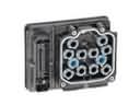 Lincoln Brake Controller
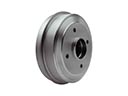 Lincoln Brake Drum
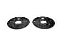 Lincoln Brake Dust Shields
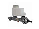 Lincoln Brake Master Cylinder
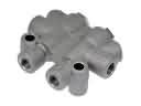 Lincoln Brake Proportioning Valve
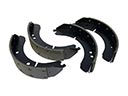 Lincoln Brake Shoe Set
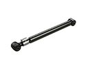 Lincoln Suspension Strut Rod
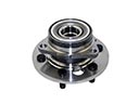 Lincoln Wheel Hub