FordParts
My Garage
My Account
Cart
OEM Mercury Montego A/C Hose
Air Conditioning Hose- Select Vehicle by Model
- Select Vehicle by VIN
Select Vehicle by Model
orMake
Model
Year
Select Vehicle by VIN
For the most accurate results, select vehicle by your VIN (Vehicle Identification Number).
2 A/C Hoses found

Mercury Montego A/C Hoses Part Number: 7F9Z-19835-AA
$122.56 MSRP: $169.55You Save: $46.99 (28%)Ships in 1-2 Business Days
Mercury Montego Discharge Line Part Number: 6F9Z-19D734-AA
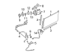
Mercury Montego A/C Hose
OEM A/C Hose boasts unmatched quality. Each part goes through full quality checks. They adhere to Mercury's official factory standards. These steps remove flaws and inconsistencies. So you can get A/C Hose with long life and a perfect fit. Come to our website and find genuine Mercury Montego parts. We keep a wide inventory of OEM Montego parts at the highly affordable prices. It's easy to search, compare, and pick what you need. You'll love the clear info and simple checkout. We offer top-rated customer service, and we reply fast. We also ship promptly to ensure your order arrives on time.
A/C Hose is used for the climate control system of Mercury Montego vehicles popular for their quality and reliability. This A/C Hose assists in transportation of refrigerant given that it removes heat from the cabin to give more comfortable ride for the driver. Specifically built to handle pressure that is characteristic of refrigerant when it is in its gaseous state the A/C Hose is equipped with crimped aluminum alloy ends that make it leakage proof and highly durable. Its universality can be noted as it fits noticeably different generations of the Montego models, starting from 1968 and up to the last models available on the market in 2007. A/C Hose, in the same way, improves the functionality of the air conditioning system, and at the same time, it contributes to operating temperature to serve the interest of passengers. Some unique aspects of the automotive market include high pressure and leaks, which makes the Mercury Montego /A/C Hose the premier since it is resistant to high pressure and does not leak. Showing both performance and durability the A/C Hose reflects the overall quality Mercury vehicles are built with, to give only the premier comfort and protection when on the road. Again, the A/C Hose is one of the notable part that play a crucial role in increasing general performance and security of Mercury Montego series.
Mercury Montego A/C Hose Parts and Q&A
- Q: How to Service the A/C Hose for the Auxiliary Evaporator Outlet and Inlet Lines on Mercury Montego?A:A necessary first step when servicing auxiliary evaporator outlet and inlet lines is to make sectioned cuts in the underbody auxiliary lines so they become removable easily while also maintaining proper identification of the cut line(s). The auxiliary evaporator inlet and outlet lines arrive to customers in two-piece format for direct installation. Recovery of the refrigerant must begin before removal of the exhaust Muffler. Below are the steps for removing the rear driveshaft when servicing AWD vehicles. Secondly remove the exhaust heat shield followed by the procedure to disconnect and discard the O-ring seal on the auxiliary evaporator inlet line fitting and finally tighten the new fitting at 8Nm torque (71lb-in). Use this procedure again for the outlet line of the auxiliary evaporator. Begin the procedure by taking off the LH rear wheel and quarter panel moulding and then move on to unscrew the bracket bolts on both sides of the outer and inner LH rear quarter panel moulding. Finish by removing the bracket from the vehicle. After removing the LH rear Brake Caliper bolts positioning it aside you will tighten them to 35 Nm (26 lb-ft) when reinstalling. During reinstallation replace the Parking Brake Cable bolts by tightening them to 12 Nm (9 lb-ft). The repair process for AWD vehicles involves removing rear subframe bracket bolts and lower Control Arm bolt but requires torquing them to 63 Nm (46 lb-ft) and 90 Nm (66 lb-ft) when reinstalling these components. During reinstallation of the LH lower shock bolt keep torque at 142 Nm (105 lb-ft). Use a lifting table to support the rear subframe before taking out the LH rear subframe bolts; position the lowered subframe and torques these bolts to 115 Nm (85 lb-ft). The technician should support the fuel tank yet remove the LH rear fuel tank strap bolt before tightening it to 35 Nm (26 lb-ft) for reinstallation. Archive the rear auxiliary inlet and outlet line fitting nuts together with their O-ring seals whereas new fittings require 8 Nm (71 lb-in) torque when they are installed. Replace the middle rear and front auxiliary line brackets along with their bolts and nuts yet tighten them at 5 Nm (44 lb-in) after reinstalling the brackets. Follow these procedures to differentiate the lines and then position the replacement lines in the original spot before cutting the auxiliary evaporator lines in the exact location as the middle fitting. The procedure requires disconnecting middle auxiliary evaporator line fittings while unmounting and removing both front and rear auxiliary line brackets and their segments of evaporator line. Installation completion requires the exact opposite steps of removal alongside new O-ring seals, proper PAG oil lubrication of the refrigeration system followed by evacuation and leak testing until system pressurization.

Related Mercury Montego Parts
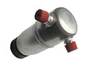 Mercury Montego A/C Accumulator
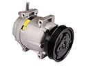 Mercury Montego A/C Compressor
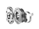 Mercury Montego A/C Compressor Clutch
 Mercury Montego A/C Compressor Cut-Out Switches
 Mercury Montego A/C Condenser
 Mercury Montego A/C Expansion Valve
 Mercury Montego A/C Idler Pulley
 Mercury Montego Blend Door Actuator
 Mercury Montego Blower Motor Resistor
 Mercury Montego Evaporator
 Mercury Montego Heater Core
 Mercury Montego HVAC Pressure Switch
Browse Mercury Montego A/C Hose by Years
2007
2006
2005