FordParts
My Garage
My Account
Cart
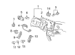
OEM 2007 Ford Freestar Brake Pedal
Brake Pedal Pad- Select Vehicle by Model
- Select Vehicle by VIN
Select Vehicle by Model
orMake
Model
Year
Select Vehicle by VIN
For the most accurate results, select vehicle by your VIN (Vehicle Identification Number).
2 Brake Pedals found

2007 Ford Freestar Pedal Assembly Part Number: 3F2Z-2455-BA
Product Specifications- Other Name: Pedal Assembly - Brake
- Base No.: 2455
- Item Weight: 5.90 Pounds
- Condition: New
- Fitment Type: Direct Replacement
- SKU: 3F2Z-2455-BA
- Warranty: This genuine part is guaranteed by Ford's factory warranty.
2007 Ford Freestar Pedal Assembly Part Number: 3F2Z-2455-AA
Product Specifications- Other Name: Pedal Assembly - Brake
- Base No.: 2455
- Item Weight: 13.80 Pounds
- Condition: New
- Fitment Type: Direct Replacement
- SKU: 3F2Z-2455-AA
- Warranty: This genuine part is guaranteed by Ford's factory warranty.
2007 Ford Freestar Brake Pedal
If you're seeking quality and affordability, look no further than our extensive inventory of genuine 2007 Ford Freestar Brake Pedal available at FordPartsDeal.com. You can confidently purchase our OEM 2007 Ford Freestar Brake Pedal as they are supported by the manufacturer's warranty and our hassle-free return policy, alongside the benefit of our fast delivery service.
2007 Ford Freestar Brake Pedal Parts Q&A
- Q: How to service and repair the brake pedal assembly on 2007 Ford Freestar?A: Service and repair procedures for the brake pedal assembly start with positioning adjustable pedals to their maximum forward extent. The repair process starts with bolt removal from the steering column opening cover before taking off the cover and tightening those bolts to 8 Nm (71 inch lbs) when reattaching them. Afteruntaking two bolts off from the steering column opening reinforcement you should remove the reinforcement piece which requires 8 Nm (71 inch lbs) torque when reinstalling. Remove the left-hand side demister duct followed by disconnection of the upper bolt of the steering intermediate shaft which should be set aside for reinstallation while torquing the bolt to 30 Nm (22 ft. lbs). First remove the redundant self-locking clip cover and the self-locking clip before placing the brake pedal position (BPP) switch nearby the booster rod with bushing set aside from the brake pedal. The procedure requires users to disconnect the adjustable pedal motor electrical connector which sits atop the bracket and to unfasten the accelerator cable both from the pedal arm and the plastic plunger. The technician first tightens each brake booster nut to 25 Nm (18 ft. lbs) before removing them followed by the removal of both upper brake pedal bracket bolts to be tightened to 25 Nm (18 ft. lbs) upon reinstallation. The last step includes removing the brake pedal and bracket assembly before you revert the installation procedure.
Related 2007 Ford Freestar Parts
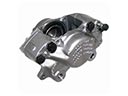 2007 Ford Freestar Brake Caliper
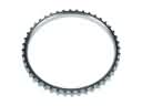 2007 Ford Freestar ABS Reluctor Ring
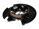 2007 Ford Freestar Brake Backing Plate
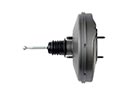 2007 Ford Freestar Brake Booster
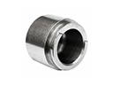 2007 Ford Freestar Brake Caliper Piston
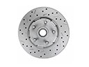 2007 Ford Freestar Brake Disc
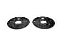 2007 Ford Freestar Brake Dust Shields
 2007 Ford Freestar Brake Line
 2007 Ford Freestar Brake Master Cylinder
 2007 Ford Freestar Hydraulic Hose
 2007 Ford Freestar Parking Brake Cable
 2007 Ford Freestar Wheel Hub