FordParts
My Garage
My Account
Cart
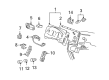
OEM 2006 Ford Freestar Brake Pedal
Brake Pedal Pad- Select Vehicle by Model
- Select Vehicle by VIN
Select Vehicle by Model
orMake
Model
Year
Select Vehicle by VIN
For the most accurate results, select vehicle by your VIN (Vehicle Identification Number).
2 Brake Pedals found

2006 Ford Freestar Pedal Assembly Part Number: 3F2Z-2455-BA
Product Specifications- Other Name: Pedal Assembly - Brake
- Base No.: 2455
- Item Weight: 5.90 Pounds
- Condition: New
- Fitment Type: Direct Replacement
- SKU: 3F2Z-2455-BA
- Warranty: This genuine part is guaranteed by Ford's factory warranty.
2006 Ford Freestar Pedal Assembly Part Number: 3F2Z-2455-AA
Product Specifications- Other Name: Pedal Assembly - Brake
- Base No.: 2455
- Item Weight: 13.80 Pounds
- Condition: New
- Fitment Type: Direct Replacement
- SKU: 3F2Z-2455-AA
- Warranty: This genuine part is guaranteed by Ford's factory warranty.
2006 Ford Freestar Brake Pedal
If you're seeking quality and affordability, look no further than our extensive inventory of genuine 2006 Ford Freestar Brake Pedal available at FordPartsDeal.com. You can confidently purchase our OEM 2006 Ford Freestar Brake Pedal as they are supported by the manufacturer's warranty and our hassle-free return policy, alongside the benefit of our fast delivery service.
2006 Ford Freestar Brake Pedal Parts Q&A
- Q: How to service and repair the brake pedal assembly on 2006 Ford Freestar?A: In order to service brake pedal assembly, adjust pedals (where necessary), remove steering column cover and reinforcement, and disassemble demister duct. Disengage steering shaft, BPP switch and brakes. Disassemble brake booster and bracket bolts, reassemble by reversing the process, and make certain that torque specifications are met.
Related 2006 Ford Freestar Parts
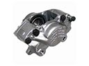 2006 Ford Freestar Brake Caliper
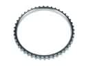 2006 Ford Freestar ABS Reluctor Ring
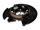 2006 Ford Freestar Brake Backing Plate
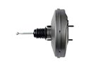 2006 Ford Freestar Brake Booster
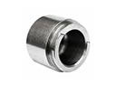 2006 Ford Freestar Brake Caliper Piston
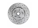 2006 Ford Freestar Brake Disc
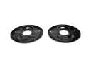 2006 Ford Freestar Brake Dust Shields
 2006 Ford Freestar Brake Line
 2006 Ford Freestar Brake Master Cylinder
 2006 Ford Freestar Hydraulic Hose
 2006 Ford Freestar Parking Brake Cable
 2006 Ford Freestar Wheel Hub