FordParts
My Garage
My Account
Cart
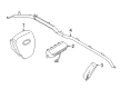
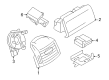
OEM Ford F-350 Super Duty Air Bag
Air Bag Module- Select Vehicle by Model
- Select Vehicle by VIN
Select Vehicle by Model
orMake
Model
Year
Select Vehicle by VIN
For the most accurate results, select vehicle by your VIN (Vehicle Identification Number).
69 Air Bags found


Ford F-350 Super Duty Driver Air Bag Part Number: 6C3Z-25043B13-AAC
$580.44 MSRP: $859.92You Save: $279.48 (33%)


Ford F-350 Super Duty Driver Inflator Module Part Number: BC3Z-25043B13-AB
$208.41 MSRP: $306.03You Save: $97.62 (32%)

Ford F-350 Super Duty Inflator Curtain, Driver Side Part Number: BC3Z-26042D95-B
$1087.75 MSRP: $1611.48You Save: $523.73 (33%)Ships in 1-3 Business Days

Ford F-350 Super Duty Driver Inflator Module Part Number: HC3Z-25043B13-BA
$501.28 MSRP: $736.10You Save: $234.82 (32%)Ford F-350 Super Duty Inflator Curtain, Passenger Side Part Number: BC3Z-28042D94-C
$881.29 MSRP: $1398.87You Save: $517.58 (37%)Ships in 1-3 Business DaysFord F-350 Super Duty Inflator Curtain, Driver Side Part Number: BC3Z-28042D95-C
$944.24 MSRP: $1398.87You Save: $454.63 (33%)Ships in 1-2 Business Days
Ford F-350 Super Duty Inflator Curtain, Passenger Side Part Number: PC3Z-28042D94-A
$503.62 MSRP: $739.53You Save: $235.91 (32%)Ships in 1-2 Business Days
Ford F-350 Super Duty Passenger Air Bag Part Number: PC3Z-99044A74-A
$438.20 MSRP: $643.47You Save: $205.27 (32%)Ships in 1-2 Business Days
Ford F-350 Super Duty Inflator Curtain, Driver Side Part Number: LC3Z-16042D95-C
$505.77 MSRP: $802.82You Save: $297.05 (37%)Ships in 1-2 Business Days
Ford F-350 Super Duty Driver Air Bag Part Number: HC3Z-25043B13-AF
$268.11 MSRP: $393.70You Save: $125.59 (32%)Ships in 1-3 Business DaysFord F-350 Super Duty Driver Inflator Module Part Number: HC3Z-25043B13-BE
$351.43 MSRP: $516.05You Save: $164.62 (32%)Ships in 1-2 Business DaysFord F-350 Super Duty Driver Inflator Module Part Number: HC3Z-25043B13-AD
$252.76 MSRP: $393.70You Save: $140.94 (36%)Ships in 1-3 Business Days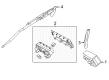
Ford F-350 Super Duty Head Air Bag, Driver Side Part Number: GC3Z-25042D95-A
$1176.09 MSRP: $1742.35You Save: $566.26 (33%)Ships in 1-3 Business Days
Ford F-350 Super Duty Inflator Curtain, Passenger Side Part Number: PC3Z-26042D94-A
$541.90 MSRP: $802.82You Save: $260.92 (33%)Ships in 1-2 Business DaysFord F-350 Super Duty Inflator Curtain, Passenger Side Part Number: BC3Z-25042D94-B
$752.99 MSRP: $1115.53You Save: $362.54 (33%)Ships in 1-3 Business DaysFord F-350 Super Duty Head Air Bag, Passenger Side Part Number: GC3Z-25042D94-A
$423.71 MSRP: $622.18You Save: $198.47 (32%)Ships in 1-3 Business Days
Ford F-350 Super Duty Driver Inflator Module Part Number: PC3Z-25043B13-AD
$248.78 MSRP: $365.32You Save: $116.54 (32%)Ships in 1-2 Business DaysFord F-350 Super Duty Driver Inflator Module Part Number: PC3Z-25043B13-BA
$251.85 MSRP: $369.82You Save: $117.97 (32%)Ships in 1-2 Business Days
Ford F-350 Super Duty Passenger Air Bag, Upper Part Number: AC3Z-25044A74-AA
$226.66 MSRP: $353.05You Save: $126.39 (36%)Ships in 1-2 Business Days
| Page 1 of 4 |Next >
1-20 of 69 Results
Ford F-350 Super Duty Air Bag
OEM Air Bag boasts unmatched quality. Each part goes through full quality checks. They adhere to Ford's official factory standards. These steps remove flaws and inconsistencies. So you can get Air Bag with long life and a perfect fit. Come to our website and find genuine Ford F-350 Super Duty parts. We keep a wide inventory of OEM F-350 Super Duty parts at the highly affordable prices. It's easy to search, compare, and pick what you need. You'll love the clear info and simple checkout. We offer top-rated customer service, and we reply fast. We also ship promptly to ensure your order arrives on time.
Ford F-350 Super Duty Air Bag Parts and Q&A
- Q: How should the driver air bag module be serviced to prevent serious injury from accidental deployment on Ford F-350 Super Duty?A:The driver air bag module requires a specific service approach that includes always holding or placing it with the air bag and deployment door/trim cover/tear seam pointed toward a safe direction away from the body. This precaution prevents serious injuries in case of accidental deployment. Probing electrical connectors on air bag and Safety Canopy(R) and side air curtain modules will cause accidental deployment that increases the danger of fatal injuries. Unplug the three driver air bag module wire clips fully from their respective hooks on the steering wheel before extraction to defend against damaging the module. An air bag warning indicator will turn on when replacing the correct Restraints Control Module (RCM) fuse while the ignition is ON and a fully operational Supplemental Restraint System (SRS) with no faults must exist for releasing the vehicle to customers. The first step should include disabling the SRS system while facing the wheels straight forward plus centering the tilted steering wheel when present. A left turn of the wheel to the 9 o'clock position allows access to the driver air bag module geometric clips without damaging the Steering Column multifunction switch. Proceed by taking out the screw and tilt lever (if present) and then the three screws to access the steering column shroud before removing both shrouds. A mirror will help you locate the three driver air bag module wire clips situated at the rear of the steering wheel and you can effortlessly detach them using a screwdriver or similar tool by pushing each clip toward the center of the wheel. The technician should disconnect the driver air bag module together with the horn switch electrical connections before extracting the driver air bag module from the steering wheel. The installation process requires connecting the electrical connectors for the horn switch and driver air bag module and setting the driver air bag module onto the steering wheel to align locator pins before using firm pressure to attach the three wire clips. Secure the steering column lower and upper shrouds by tightening their three lower screws and install the tilt lever component followed by its screw while applying 6 Nm (53 lb-in) torque. Finally, repower the SRS.
- Q: How to arm and disarm the air bag and safety belt pretensioner restraint system on Ford F-350 Super Duty?A:You can activate or deactivate the air bag and safety belt pretensioner restraint system built after 10/2/2000 by putting the Ignition Switch between the OFF and RUN positions using air bag modules and safety belt pretensioner or restraint system diagnostic tools to monitor the air bag indicator. The air bag indicator will remain on continuously for six seconds and then it will turn OFF. The air bag indicator operates differently when a Supplemental Restraint System fault exists because the indicator turns off or flashes after thirty seconds of ignition at RUN position as the Restraints Control Module (RCM) completes its necessary checks. The air bag indicator must be repaired immediately if it is unresponsive while an SRS fault exists because the system will emit a five times five beep sequence as an alert.


Related Ford F-350 Super Duty Parts
 Ford F-350 Super Duty Air Bag Control Module
 Ford F-350 Super Duty Air Bag Sensor
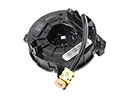 Ford F-350 Super Duty Clock Spring
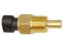 Ford F-350 Super Duty Coolant Temperature Sensor
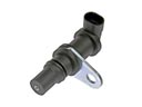 Ford F-350 Super Duty Crankshaft Position Sensor
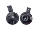 Ford F-350 Super Duty Horn
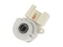 Ford F-350 Super Duty Ignition Switch
 Ford F-350 Super Duty Neutral Safety Switch
 Ford F-350 Super Duty Oxygen Sensors
 Ford F-350 Super Duty Parking Assist Distance Sensor
 Ford F-350 Super Duty Throttle Position Sensor
 Ford F-350 Super Duty Transmitter