FordParts
My Garage
My Account
Cart
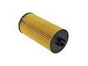
OEM Ford Flex Camshaft
Cam- Select Vehicle by Model
- Select Vehicle by VIN
Select Vehicle by Model
orMake
Model
Year
Select Vehicle by VIN
For the most accurate results, select vehicle by your VIN (Vehicle Identification Number).
14 Camshafts found


Ford Flex Intake Camshaft, Passenger Side Part Number: AA5Z-6250-A
$117.94 MSRP: $171.67You Save: $53.73 (32%)Ships in 1-3 Business Days


Ford Flex Camshaft, Passenger Side Part Number: 7T4Z-6250-C
$143.58 MSRP: $209.00You Save: $65.42 (32%)

Ford Flex Camshaft, Driver Side Part Number: 7T4Z-6250-B
$206.00 MSRP: $302.50You Save: $96.50 (32%)
Ford Flex Exhaust Camshaft, Passenger Side Part Number: AT4Z-6250-H
$89.35 MSRP: $137.50You Save: $48.15 (36%)
Ford Flex Exhaust Camshaft, Driver Side Part Number: AT4Z-6250-J
$94.81 MSRP: $138.00You Save: $43.19 (32%)Ford Flex Intake Camshaft, Driver Side Part Number: AT4Z-6250-G
$94.81 MSRP: $138.00You Save: $43.19 (32%)Ships in 1-3 Business Days
Ford Flex Exhaust Camshaft, Driver Side Part Number: AA5Z-6250-D
$112.78 MSRP: $164.17You Save: $51.39 (32%)Ships in 1-3 Business DaysFord Flex Exhaust Camshaft, Passenger Side Part Number: AA5Z-6250-C
$113.01 MSRP: $164.50You Save: $51.49 (32%)Ships in 1-3 Business Days
Ford Flex Intake Camshaft, Passenger Side Part Number: AT4Z-6250-F
$162.00 MSRP: $250.00You Save: $88.00 (36%)Ships in 1-3 Business DaysFord Flex Intake Camshaft, Driver Side Part Number: AA5Z-6250-B
$399.52 MSRP: $586.67You Save: $187.15 (32%)Ships in 1-3 Business Days

Ford Flex Camshaft, Passenger Side Part Number: 7T4Z-6250-A
Ford Flex Camshaft, Driver Side Part Number: 7T4Z-6250-D
$180.11 MSRP: $262.17You Save: $82.06 (32%)Ford Flex Camshaft, Driver Side Part Number: 9T4Z-6250-B

Ford Flex Camshaft, Passenger Side Part Number: 9T4Z-6250-A
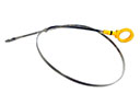
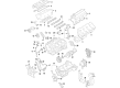
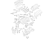
Ford Flex Camshaft
OEM Camshaft boasts unmatched quality. Each part goes through full quality checks. They adhere to Ford's official factory standards. These steps remove flaws and inconsistencies. So you can get Camshaft with long life and a perfect fit. Come to our website and find genuine Ford Flex parts. We keep a wide inventory of OEM Flex parts at the highly affordable prices. It's easy to search, compare, and pick what you need. You'll love the clear info and simple checkout. We offer top-rated customer service, and we reply fast. We also ship promptly to ensure your order arrives on time.
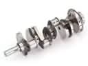
Camshaft is an important part which dramatically improves the performance and durability of the Ford Flex series of cars. Known for its durability the camshaft is that particular component that controls the opening and closing of the intake and exhaust valves to facilitate the right amount of air and fuel consumption in the engine's cylinder. Made of materials such as iron or steel, the Camshaft comes in Over Head Valve (OHV), Single Over Head Cam (SOHC) and Double Over Head Camshaft (DOHC) depending with the performance of the distinct Flex models. For instance, in the DOHC setup, a greater amount of control can be exercised over the valves, and hence there can be better intake and exhaust outputs, which will mean better power and efficiency rates. Details like LSA greatly affect the torque and idle quality which makes the Camshaft an important component to harness the full potential of the engine. This camshaft enhances the performance of the vehicle and also improves on the safety and efficiency of the Ford Flex hence suitable for any tribes, couples or families or even single individuals. The Camshaft is, therefore, a marked improvement on the general Flex models in the automotive market since it is compatible with many Flex models and can simultaneously improve the dynamics of the car and uphold the Ford brand's reputation of durability. Due to the excellent engineering of the Camshaft, drivers can revel in powerful and smooth rides which gives the Camshaft a central place in the design of the Ford Flex.
Ford Flex Camshaft Parts and Q&A
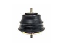
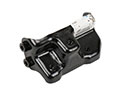
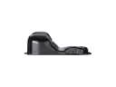
- Q: What precautions should be taken when removing and replacing the camshaft to prevent ignition and ensure proper installation on Ford Flex?A:The presence of smoking and open flames by the fuel-related components should be avoided when changing and installing the camshaft as highly flammable mixtures represent a risk of ignition. Clean work areas should always be maintained to stop foreign substances which result in engine breakdowns. The Crankshaft must remain free spinning with its freewheeling position set at 9 o'clock throughout the time when checking valve clearance and installing camshafts. Turn the crankshaft to the 9 o'clock direction counterclockwise. Engine oil coating on the camshafts must be performed before their installation onto the LH and RH cylinder heads while maintaining their neutral position. First install the 8 camshaft caps and 16 bolts on the specified sequence before tightening them to 10 Nm (89 lb-in). Inspection with a feeler gauge will determine engine valve clearance requirements after new component installation. In case adjustments need new valve tappets of proper dimensions. Install the Camshaft Holding Tool while the LH camshafts face Top Dead Center (TDC) then proceed to assemble the Variable Camshaft Timing (VCT) assembly and exhaust camshaft sprocket with secondary timing chain that aligns its colored links to timing marks. The bolts should be tightened in four specific stages while removing the LH secondary Timing Chain Tensioner lockpin. Follow this procedure one more time for the RH camshafts to achieve proper component alignment throughout the tightening process. The mechanism starts with rotating the crankshaft to its TDC position at a 60-degree counterclockwise orientation before installing the primary timing chain with linked colors matching precisely. Then install and position the tensioning equipment and guide for the lower primary chain before resetting both devices properly and aligning timing markings accurately. You should install new VCT housing seals on the cylinder head and make sure dowels fully penetrate the opening before securing both VCT housings to 10 Nm (89 lb-in). Use Motorcraft High Performance Engine RTV Silicone to coat the engine front cover sealing areas before you install the front cover and tighten its bolts in order starting with 3 Nm (27 lb-in). Quite the brake by which to install the engine mount bracket with all engine front cover bolts yet apply two tightening stages. Before placing the engine mount studs apply clean thread sealer to them. You should add the crankshaft front seal along with the crankshaft pulley while using specific tightening sequences for the pulley bolt. Put all necessary seals in place before installing the valve covers with RTV sealant applied to their joints. The accessory drive belt tensioner and Power Steering Pump must be correctly positioned at this stage. All electrical wire retaining devices should be connected and after upper engine failure repairs check for metal debris in the Intake Manifold before installing new gaskets with bolt torques set to 10 Nm (89 lb-in). You must place the upper intake manifold support bracket bolt while connecting the Throttle Body electrical connector along with installing the fuel tube bracket bolt.
- Q: How to Remove and Replace a Camshaft on Ford Flex?A:Before replacing the camshaft the area needs to be completely clean to avoid allowing foreign debris from damaging engine functionality. You should begin by extracting the transaxle mount through bolt and nut and subsequent elimination of the bolt together with three nuts as well as the transaxle mount bracket. Begin the procedure by taking out the nut and bolt along with the Engine Mount brace before continuing with removal of the four engine mount nuts and three bolts from the mount. Lower the engine along with transaxle assembly from the vehicle then disconnect both the PCV hose from the PCV valve and the Throttle Body electrical connector. First remove the wiring harness retainers from the upper intake manifold before taking out the upper intake manifold support bracket bolt and the wire harness pin-type retainer and fuel tube bracket bolt from that same area. Any observed metal debris within the intake manifold requires replacement with a new manifold because of the upper engine failure. Six bolts need removal before extracting the upper intake manifold with disposal of its gaskets. Disconnect the electrical connectors for RH Catalyst Monitor and RH VCT Solenoid together with the three RH Coil-On-Plug Electrical Connectors. Starting on the right side, remove the valve cover wire retainers while disconnecting the LH VCT solenoid together with the three LH coil-on-plug electrical connectors followed by the removal of wire retainers from the left valve cover. The installation requires removing six bolts, six coil-on-plug assemblies, separating the PSP switch electric connector and taking out the PSP tube bracket-to-Power Steering Pump bolt. First separate the PSP tube bracket from the RH valve cover stud bolt by removing its nut and bolt components before placing the power steering pump aside. First remove the accessory drive belt tensioner's three bolts before starting to loosen the eleven stud bolts. Proceed to remove the LH valve cover by discarding its gasket. You need to remove the RH valve cover after loosening its bolt and ten stud bolts and discarding the gasket. The VCT solenoid seals and spark plug tube seals require inspection for damage; replace damaged ones using VCT Spark Plug Tube Seal Remover and Handle. A Strap Wrench should remove the Crankshaft bolt accompanied by its washer until the bolt requires discarding before moving to the 3-Jaw Puller to extract the crankshaft pulley and implementing the Oil Seal Remover for crankshaft front seal removal. Use hand tools only to remove the two engine mount studs after removing the engine mount bracket and the two bolts simultaneously. The procedure starts with bolts removal from the bracket followed by the engine mount before moving on to engine front cover bolts removal totaling twenty-two. Tighten six front cover bolts installed into the engine front cover holes but only finger-tight until the cylinder block-to-front cover seal is detached before removing the cover. Use a 3M Roloc(R) Bristle Disk (2-in white, part number 07528) on medium speed (15,000 rpm) to clean the engine front cover before washing it to eliminate all foreign substances. Engine maintenance requires users to position clean shop towels on open engine cavities before removing them gently to stop material from entering the engine. Remove large silicone and gasket material Then apply silicone remover and metal surface prep to wash off any traces of oil or coolant from the cylinder head sealing surfaces along with the Oil Pan and cylinder block surfaces. The two locating dowel pins should be properly seated in the cylinder block before rotating the crankshaft clockwise to match VCT assembly timing marks. A Camshaft Holding Tool should be attached to both LH and RH camshaft flats to maintain positions at Top Dead Center. The service technician should remove three bolts from the RH VCT housing together with three bolts from the LH VCT housing before discarding the VCT housing seals. Proceed by first removing two bolts from the primary Timing Chain Tensioner then discard the tensioner before taking out the tensioner arm followed by the lower LH primary timing chain guide bolts and finally extract the primary timing chain. Install a proper locking pin on the compressed LH secondary timing chain tensioner to maintain its collapsed position. Continue by removing the LH VCT assembly with its secondary timing chain, LH exhaust camshaft sprocket and attached assembly, along with the LH VCT assembly bolt and the LH exhaust camshaft sprocket bolt. The Camshaft Holding Tool needs removal from the LH camshafts while keeping them in their neutral position to avoid engine damage. Unfasten the bolts that hold the LH camshaft bearing caps and afterwards remove the LH camshafts. Begin RH camshaft procedures by compressing the RH secondary timing chain tensioner before installation of the lockpin and discarding the RH VCT assembly bolt and RH exhaust camshaft sprocket bolt. Proceed with removing the RH VCT assembly along with the secondary timing chain and RH exhaust camshaft sprocket as one unit. Before extracting the bolts and RH camshaft bearing caps together with the RH camshafts the Camshaft Holding Tool needs to be removed and the camshafts must face neutral TDC.