
Popular OEM Ford Flex Parts
- Body & Hardware Parts View More >
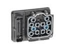
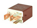
- Electrical Parts View More >
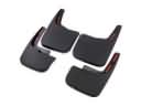
- Interior & Exterior Trim Parts View More >
- Air & Fuel Delivery Parts View More >
- Steering Parts View More >
- Emission Control & Exhaust Parts View More >
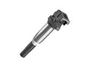
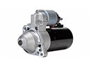
- Charging & Starting Parts View More >
- Engine Parts View More >
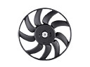
- Belts & Cooling Parts View More >
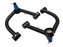
- Suspension Parts View More >
- Brakes Parts View More >
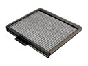
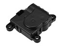
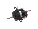
- A/C & Heating Parts View More >


Why Buy Genuine Ford Flex Parts From FordPartsDeal.com
FordPartsDeal.com offers a smart and convenient way to buy genuine parts online. We sell new OEM Ford Flex parts, including Headlights & Lighting. Authorized dealers directly provide all the Ford Flex parts and assemblies to ensure the optimal quality and fit. We also provide all properly fitting Ford Flex parts, such as Transmission, Driveline & Axles specific to your model. When you shop here, you get real Ford value at highly competitive prices. All our products come with the same Ford warranty available at other dealerships. Our easy-to-use catalog helps you quickly identify the right part for your car. You'll receive fast shipping from our warehouse network, keeping your Ford Flex running smoothly. Our staff consists of Ford professionals who are ready to assist you. We aim to treat each customer as if they were stepping out of a Ford showroom. VIN verification and our live support ensure that the part you order is the right Ford Flex part for your vehicle.
The full-size SUV segment received its important new addition through the Ford Flex which rolled out in 2009 before its production ceased in 2019. The Ford Flex is built on the D4 platform and offers two engine options: a 3.5L Duratec V6 engine and a more powerful 3.5L EcoBoost V6 engine, which delivers 365 horsepower starting with the 2013 model year. The vehicle uses two specific and competent power platforms of 6-speed automatic transmission for optimized driving capabilities. The Ford Flex offers either front-wheel drive (FWD) or all-wheel drive (AWD) options, ensuring versatility in various driving conditions. A Ford Flex model can easily host six or seven passengers due to its 4,468 lb FWD base weight that rises to 4,640 lb when using the AWD system. Its 117.9-inch wheelbase provides plenty of interior space. The dimensions of the vehicle consist of 201.8 inches for length and 75.9 inches for width and 68 inches for height and this combination creates substantial interior space with rear parking sensors and an 8-inch touchscreen display present only in higher trims. Manufacturers have regularly updated minor components of the Ford Flex production since its inception while maintaining its market relevance. As a Ford Flex owner one should use genuine Ford parts to preserve their vehicle because these components meet the factory standards which guarantee performance reliability.
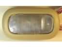
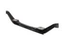
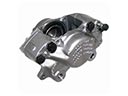
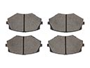
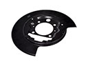
Ford Flex issues group into interior hardware, front braking, and driveline sealing. In the cabin, a broken center console latch causes a loose lid and poor retention. Replacement of the center console latch restores latching and normal function on the Flex. For braking, defective front caliper anchor brackets can grind rotors and eat brake pads quickly. Noise during stops and dust on wheels often appear. Replace the brackets with updated pieces, install new rotors and brake pads, then bed them. Inspect hose routing and confirm even clamping on the Flex. In the driveline, leaks at the axle area point to a failing axle shaft seal or PTU cover seal. Transmission fluid may show red, PTU fluid appears brown on the Flex. Replace the axle shaft seal or reseal the PTU as required. Clean the case, check venting, and verify fluid level after service. A brief road test confirms quiet braking and dry housings. Ford guidance recommends torque checks on hardware after heat cycles. Regular inspections keep the Flex reliable between services. Follow Ford procedures for seal installation depth and bracket torque. Finishing steps include a brake feel check and a short alignment sweep on the Ford Flex.
Ford Flex Parts and Q&A
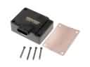
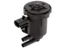
- Q: What safety precautions should be observed when servicing the fuel gauge sender and fuel pump module on Ford Flex?A:Be careful when servicing the fuel gauge sender and pump module because they contain flammable mixtures. Take off fuel pressure, disconnect battery and clean connections. Take out the pump module, fill up fuel and look at the damage. Where needed, change module/ tank, then put on a new O-ring and lock-ring, but be careful to align them.
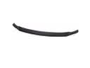
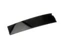
- Q: How to remove and replace the front bumper cover on Ford Flex?A:To change the front bumper cover, make sure that the car has neutral on a hoist. Take away upper scrivets and bolts, middle scrivets, lower air deflector scrivets. Switch off fog lamps when fitted. draw up the upper part and the cover will come away, examine reinforcements, and then in the same way re-fasten.
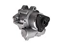
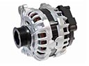
- Q: How to service and repair the alternator on Ford Flex?A:In order to fix the alternator, you have to remove the protective cover, disconnect battery, and the electrical connector. Take-off cooling fan system and accessory drive belt. Removal of the generator followed by reinstatement, all bolts should be tightened to required torque. Reattach the power parts and power cable.


