FordParts
My Garage
My Account
Cart
OEM Mercury Sable Air Bag
Air Bag Module- Select Vehicle by Model
- Select Vehicle by VIN
Select Vehicle by Model
orMake
Model
Year
Select Vehicle by VIN
For the most accurate results, select vehicle by your VIN (Vehicle Identification Number).
58 Air Bags found

Mercury Sable Passenger Air Bag Part Number: F8DZ-54044A74-AAA
$115.91 MSRP: $160.35You Save: $44.44 (28%)Ships in 1-2 Business DaysMercury Sable Passenger Air Bag, Denim Blue Part Number: F8DZ-54044A74-AAB
$120.31 MSRP: $166.43You Save: $46.12 (28%)Ships in 1-2 Business DaysMercury Sable Passenger Air Bag Part Number: F8DZ-54044A74-AAF
$193.19 MSRP: $267.25You Save: $74.06 (28%)Ships in 1-2 Business Days
Mercury Sable Passenger Air Bag, Black, Upper Part Number: 6F1Z-54044A74-AC
$123.26 MSRP: $170.52You Save: $47.26 (28%)Ships in 1-2 Business Days
Mercury Sable Driver Air Bag Part Number: XF1Z-54043B13-BAA
$90.89 MSRP: $125.74You Save: $34.85 (28%)Ships in 1-2 Business Days
Mercury Sable Inflator Curtain, Driver Side Part Number: 8G1Z-54042D95-A
$102.34 MSRP: $141.58You Save: $39.24 (28%)Ships in 1-2 Business DaysMercury Sable Driver Inflator Module Part Number: F7DZ-54043B13-AAH
$69.87 MSRP: $96.65You Save: $26.78 (28%)Ships in 1-2 Business DaysMercury Sable Passenger Air Bag, Denim Blue Part Number: F8DZ-54044A74-AAE
$173.77 MSRP: $240.40You Save: $66.63 (28%)Ships in 1-2 Business DaysMercury Sable Passenger Air Bag, Willow Green Part Number: F7DZ-54044A74-AAG
$120.31 MSRP: $166.43You Save: $46.12 (28%)Ships in 1-2 Business Days
Mercury Sable Driver Air Bag, Gray Part Number: F7DZ-54043B13-AAF
$65.19 MSRP: $90.18You Save: $24.99 (28%)Ships in 1-2 Business DaysMercury Sable Driver Air Bag, Willow Green Part Number: F7DZ-54043B13-AAG
$61.50 MSRP: $85.08You Save: $23.58 (28%)Ships in 1-2 Business Days
Mercury Sable Driver Air Bag Part Number: F7DZ-54043B13-AAE
$433.44 MSRP: $594.69You Save: $161.25 (28%)Ships in 1-2 Business DaysMercury Sable Driver Air Bag, Denim Blue Part Number: F8DZ-54043B13-BAB
$58.35 MSRP: $80.72You Save: $22.37 (28%)Ships in 1-2 Business DaysMercury Sable Passenger Air Bag, Willow Green Part Number: F7DZ-54044A74-AAC
$187.78 MSRP: $259.77You Save: $71.99 (28%)Ships in 1-2 Business Days
Mercury Sable Driver Air Bag Part Number: FO4Y-54043B13-A
$150.67 MSRP: $208.44You Save: $57.77 (28%)Ships in 1-2 Business DaysMercury Sable Driver Inflator Module Part Number: F8DZ-54043B13-BAA
$58.35 MSRP: $80.72You Save: $22.37 (28%)Ships in 1-2 Business Days
Mercury Sable Side Impact Inflator Module, Front Driver Side Part Number: 3F1Z-54611D11-AA
$65.62 MSRP: $90.78You Save: $25.16 (28%)Ships in 1-2 Business DaysMercury Sable Passenger Air Bag Part Number: F7DZ-54044A74-AAA
$120.31 MSRP: $166.43You Save: $46.12 (28%)Ships in 1-2 Business DaysMercury Sable Driver Air Bag, Denim Blue Part Number: XF1Z-54043B13-BAB
$78.77 MSRP: $108.97You Save: $30.20 (28%)Ships in 1-2 Business DaysMercury Sable Driver Air Bag Part Number: F8DZ-54043B13-BAC
$84.29 MSRP: $116.61You Save: $32.32 (28%)Ships in 1-2 Business Days
| Page 1 of 3 |Next >
1-20 of 58 Results
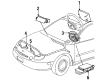
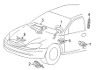
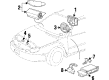
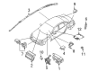
Mercury Sable Air Bag
OEM Air Bag boasts unmatched quality. Each part goes through full quality checks. They adhere to Mercury's official factory standards. These steps remove flaws and inconsistencies. So you can get Air Bag with long life and a perfect fit. Come to our website and find genuine Mercury Sable parts. We keep a wide inventory of OEM Sable parts at the highly affordable prices. It's easy to search, compare, and pick what you need. You'll love the clear info and simple checkout. We offer top-rated customer service, and we reply fast. We also ship promptly to ensure your order arrives on time.
Mercury Sable Air Bag Parts and Q&A
- Q: What are the essential disposal methods for deployed side air bag modules and safety belt pretensioners on Mercury Sable?A:It is mandatory to use the correct disposal method when disposing deployed side air bag modules from both the driver and passenger seats. Used side air bag modules with safety belt pretensioners must follow disposal procedures identical to those of scrap materials. Safety glasses should be worn whenever you work on repairing an air bag supplemental restraint system (SRS) vehicle along with all operations involving air bag modules to guard against accidental module deployment.
- Q: How should the driver air bag module be serviced to avoid accidental deployment and ensure proper installation on Mercury Sable?A:Always position driver air bag modules properly for servicing by directing the air bag main component along with deployment door and trim cover or tear seam toward the opposite direction from your body while never placing the module down with the deployment door facing the floor to prevent severe injuries. Probing the electrical connectors on air bag modules should never be attempted because accidental deployment functions could harm individuals with possibly fatal consequences. When air bag modules display discolored or damaged trim covers or deployment doors it is necessary to replace the module with a new one to guarantee proper deployment. The installation of memory saver devices raises the danger of unintended deployment so they should be avoided. The restrictions control module (RCM) air bag warning indicator becomes visible during this state because the RCM fuse is present while the ignition switch remains in the ON position. This normal warning does not imply any system malfunction. All SRS operations need to function normally and show no faults before you send the vehicle to market. The maintenance process should start with installing fresh components until the original items can be replaced to complete the diagnostic testing step once more. Begin by depowering the SRS system and unscrew the three screws attached to the steering column cover then detach the lower steering column shroud by unfastening its three screws and upper shroud untaped clamps. The process continues with removing the two screws from the instrument cluster finish panel then prying it forward together with disconnecting the in-vehicle temperature sensor assembly if present. Discard the instrument cluster finish panel with upper steering column shroud assembly after adjusting the steering column to reach maximum tilt-down position. Before removing the driver air bag module one must position the Steering Wheel to the 12 o'clock and 6 o'clock positions to access wire clips then unclip those wires from the attachment pins while lifting the module from the steering wheel. Extract electrical connections by disconnecting the two retainers attached to each device module. When installing the vehicle ensure each wire clip is placed properly on the steering wheel but you can adjust their position if needed. Steer away the steering wheel control cables from areas where driver air bag module pins anchor to stop cable pinching when you install the system. Install the two specific electrical connectors onto the driver air bag module while making sure they fit together with the intended keyway pattern without forced insertion. The correct positioning of wire clips requires removal of the driver air bag module for installation. The driver air bag module installation requires pushing it toward the steering wheel until the wire clips achieve complete engagement. Then check their securement with a mirror. The driver air bag module requires strong pulling motions from each corner for the correct attachment. Put back the instrument cluster finish panel and steering column upper shroud while connecting the in-vehicle temperature sensor assembly (when present). The instrument cluster finish panel should be secured through screws followed by installation of the lower steering column shroud through three screws then ending with the steering column cover which requires three screws. Verifying the horn operation requires checking each corner of the driver air bag module using the SRS power. Discontinue the check if the horn fails to work so inspect the horn contacts along with the steering wheel switches connector and horn wire connectors for correct attachment. Then proceed with horn fault diagnostics.


Related Mercury Sable Parts
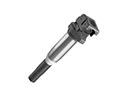 Mercury Sable Ignition Coil
 Mercury Sable Air Bag Control Module
 Mercury Sable Air Bag Sensor
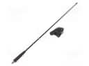 Mercury Sable Antenna
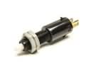 Mercury Sable Brake Light Switch
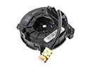 Mercury Sable Clock Spring
 Mercury Sable Crankcase Breather Hose
 Mercury Sable Crankshaft Position Sensor
 Mercury Sable Transmitter
 Mercury Sable Turn Signal Flasher
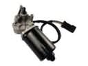 Mercury Sable Wiper Motor
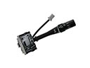 Mercury Sable Wiper Switch