FordParts
My Garage
My Account
Cart
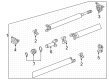
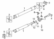
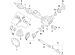
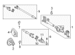
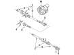
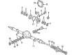
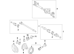
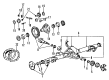
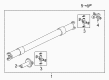
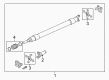
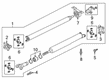
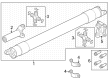
OEM Ford Universal Joint
U-Joint- Select Vehicle by Model
- Select Vehicle by VIN
Select Vehicle by Model
orMake
Model
Year
Select Vehicle by VIN
For the most accurate results, select vehicle by your VIN (Vehicle Identification Number).
32 Universal Joints found


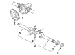
Ford Universal Joints, Front Part Number: BC3Z-4635-B
$35.95 MSRP: $52.33You Save: $16.38 (32%)Ships in 1 Business DayProduct Specifications- Other Name: Kit - Universal Joint Repair; Front, Rear, CV Joint; U Joint; U-Joint
- Position: Front
- Replaces: F2TZ-4635-E, F81Z-4635-AB


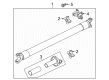
Ford Universal Joints, Rear Part Number: 7L1Z-4635-B
$37.63 MSRP: $53.83You Save: $16.20 (31%)Product Specifications- Other Name: Kit - Universal Joint Repair; Front Center, Rear, CV Joint; U Joint; U-Joint
- Manufacturer Note: 1350
- Position: Rear
- Replaces: 7L1Z-4635-A, 4L3Z-4841-FB, F5TZ-4635-A


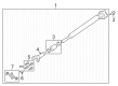
Ford Universal Joints Part Number: 6L2Z-4635-A
$62.47 MSRP: $90.93You Save: $28.46 (32%)Ships in 1-2 Business DaysProduct Specifications- Other Name: Kit - Universal Joint Repair; CV Joint; U Joint; U-Joint Kit; Universal Joint
- Manufacturer Note: Size 1330
- Replaces: 4L5Z-4635-BA


Ford U-Joint, Front Passenger Side Part Number: 5C3Z-3249-AA
$37.73 MSRP: $65.83You Save: $28.10 (43%)Product Specifications- Other Name: Kit - Universal Joint Repair; Drive Axle Shaft Universal Joint, Front Right & Left; U Joint
- Position: Front Passenger Side


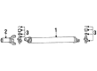
Ford Universal Joints, Front Center Part Number: BC3Z-4635-A
$29.54 MSRP: $43.00You Save: $13.46 (32%)Ships in 1-2 Business DaysProduct Specifications- Other Name: Kit - Universal Joint Repair; Front Center, Rear Center, CV Joint; U Joint; U-Joint Kit; U-Joint; Universal Joint
- Position: Front Center
- Replaces: F3TZ-4635-A, F81Z-4635-BB


Ford Universal Joints Part Number: F81Z-4635-CB
$38.33 MSRP: $54.83You Save: $16.50 (31%)Ships in 1 Business DayProduct Specifications- Other Name: Kit - Universal Joint Repair; CV Joint; U Joint
- Replaces: F81Z-4635-CA


Ford Universal Joints Part Number: 5C3Z-4635-AA
$44.27 MSRP: $63.33You Save: $19.06 (31%)Ships in 1 Business DayProduct Specifications- Other Name: Kit - Universal Joint Repair; U Joint


Ford Universal Joints, Front Driver Side Part Number: 5C3Z-3249-BA
$63.43 MSRP: $92.33You Save: $28.90 (32%)Ships in 1 Business DayProduct Specifications- Other Name: Kit - Universal Joint Repair; Drive Axle Shaft Universal Joint, Front Right & Left; U Joint; U-Joint; Universal Joint
- Position: Front Driver Side


Ford Universal Joints Part Number: 3W1Z-4635-AA
$80.40 MSRP: $111.22You Save: $30.82 (28%)Ships in 1-2 Business DaysProduct Specifications- Other Name: Kit - Universal Joint Repair; CV Joint; U Joint; Universal Joint

Ford Universal Joints Part Number: D3TZ-3249-A
$31.53 MSRP: $42.91You Save: $11.38 (27%)Product Specifications- Other Name: Kit; Universal Joint; CV Joint; U Joint; U-Joint Kit; Joint Assembly; U-Joint

Ford Universal Joints, Front Driver Side Part Number: F81Z-3249-AA
$33.61 MSRP: $47.67You Save: $14.06 (30%)Ships in 1-2 Business DaysProduct Specifications- Other Name: Kit - Universal Joint Repair; Universal Joint, Front Left, Front Right; Universal Joint; U Joint; U-Joint Kit; U-Joint
- Position: Front Driver Side
- Replaces: D8TZ-3249-A


Ford U-Joint, Rear Part Number: 4L3Z-4635-B
$110.25 MSRP: $150.03You Save: $39.78 (27%)Product Specifications- Other Name: Kit - Universal Joint Repair; Universal Joint, Front Forward, Front Rearward, Rear Forward, Rear Rearward; U Joint
- Position: Rear
- Replaces: 4L3Z-4635-AB

Ford Universal Joints, Front Part Number: HC3Z-4635-C
$59.31 MSRP: $86.33You Save: $27.02 (32%)Ships in 1-2 Business DaysProduct Specifications- Other Name: Kit - Universal Joint Repair; Front, Rear, CV Joint; U Joint; U-Joint
- Position: Front
- Replaces: HC3Z-4635-A

Ford Universal Joints Part Number: 4L3Z-4635-C
$30.79 MSRP: $43.67You Save: $12.88 (30%)Ships in 1-2 Business DaysProduct Specifications- Other Name: Kit - Universal Joint Repair; CV Joint; U Joint; U-Joint
- Replaces: 4L3Z-4635-A, E9SZ-4635-Z, F2AZ-4635-C

Ford Universal Joints, Rear Part Number: 3G3Z-4635-B
$44.20 MSRP: $64.33You Save: $20.13 (32%)Ships in 1-3 Business DaysProduct Specifications- Other Name: Kit - Universal Joint Repair; Universal Joint, Rear; CV Joint; U Joint; U-Joint
- Manufacturer Note: 1410
- Position: Rear
- Replaces: 3G3Z-4635-A

Ford Universal Joints Part Number: F1TZ-4635-C
$42.32 MSRP: $61.60You Save: $19.28 (32%)Ships in 1-3 Business DaysProduct Specifications- Other Name: Kit - Universal Joint Repair; CV Joint; U Joint; U-Joint; Universal Joint
- Replaces: F2AZ-4635-A, F1TZ-4635-A
Ford Universal Joints, Rear Part Number: HC3Z-4635-B
$76.72 MSRP: $111.67You Save: $34.95 (32%)Ships in 1-3 Business DaysProduct Specifications- Other Name: Kit - Universal Joint Repair; Universal Joint, Rear, Rear Center, Rear Forward, Rear Rearward; CV Joint; U Joint; U-Joint
- Manufacturer Note: SPL055
- Position: Rear

Ford Universal Joints, Rear Part Number: 4L5Z-4635-B
$73.68 MSRP: $107.25You Save: $33.57 (32%)Ships in 1-3 Business DaysProduct Specifications- Other Name: Kit - Universal Joint Repair; Universal Joint, Rear, Rear Center, Rear Forward, Rear Rearward; CV Joint; U Joint; U-Joint
- Position: Rear
- Replaces: 4L5Z-4635-A, 4L5Z-4635-AA, F1TZ-4635-B, F2TZ-4635-B

Ford Universal Joints Part Number: HC3Z-4635-D
$90.56 MSRP: $131.82You Save: $41.26 (32%)Ships in 1-2 Business DaysProduct Specifications- Other Name: Kit - Universal Joint Repair; U-Joint


Ford Universal Joints, Rear Part Number: BU2Z-4635-A
Product Specifications- Other Name: Kit - Universal Joint Repair; Drive Shaft Slip Yoke, Rear; CV Joint; U Joint; Flange; Coupling
- Position: Rear
- Replaces: 4L3Z-4782-AB
| Page 1 of 2 |Next >
1-20 of 32 Results
Ford Universal Joint
If you own Ford and want to keep it in top shape, choosing OEM Universal Joint is a smart move. They are precisely engineered and follow strict factory standards. They are made in advanced facilities that use cutting edge technology. Each part goes through thorough testing to confirm strength and safety, so you can trust it. FordPartsDeal.com gives you genuine Ford Universal Joint at some of the affordable online prices without cutting quality. Every OEM Ford part includes the manufacturer's warranty, easy returns, and super-fast delivery. So why wait? Shop now and get your vehicle back to peak condition.
Ford Universal Joint allows the driveshaft to rotate in a smooth and flexible way, bending with each bounce and corner. In 1903, Henry Ford began the company, and in 1913, the moving assembly line cut down the build times and costs all over the world. Ford has now matched supercharged EcoBoost with fuel-saving consumption to ensure drivers experience power and their gauges do not go down. The SYNC voice technology that switches tracks, routes, and calls without tapping fingers also comes packed in Ford. Ford takes safety to the next level with Co-Pilot360 features such as automatic braking and lane keeping, which anticipates danger before drivers. The firm has now designed electric pickups such as the F-150 Lightning that can carry heavy loads without using even a drop of gasoline. Thoughts of technology permeate each of the lineups, and it has made the everyday traveling process more comfortable, cleaner, and easier to manage. Universal Joint attaches the driveshaft to the differential to ensure that rotation remains constant as the suspension angles change on uneven roads. Universal Joint depends upon hardened cross and needle bearings in steel cups, which retain grease in place and ensure smooth motion. Types of Universal Joints differ in custom-factory greased or zerk-equipped service units, but both will address the identical twisting load without grumbling. Universal Joint advises against wear that will result in clunks and vibrations at speed and advises a driver to do something before the damage extends along the driveline.
Ford Universal Joint Parts and Q&A
- Q: How to replace a universal joint in a driveshaft on 2000-2011 Ford Ranger?A:It will be necessary to use a press or large vise for this, but it may be possible to have the driveshaft taken to a repair or machine shop for universal joint replacement at a reasonable cost. Start with the removal of the driveshaft and one should draw the position of the elements and the relation to the driveshaft tube before reassembly. It is now possible to take off the snap-rings from the spider using small pliers and to fix the driveshaft on an arbor press or, in its absence, on the working table provided with a vise. Take one bearing cap and place a pipe or a large socket over it and the other capsule place the slightly small socket over it, now use the vise or press to remove the capsule out and stop it when it gets half way out of the yoke. Screw out the cap all the way and then use the vise or large pliers to take it out completely, do the same to the opposite bearing cap. Replace all reusable components, a new U-joint must not come half and half, old parts must not be used if new ones are added. The new universal joint bearings should be packed with chassis grease in accordance with special instructions if any in this respect. Place the spider in the yoke so it rests on two bearing caps, only one of which should be threaded into place for now, and it's aligned so the output shaft comes out the bottom; make sure any grease fitting is in the right position. Spin the spider onto the bearing cap and orient it into the other partially seated cap then gently seat the bearing caps with interference that does not deform the dust seals. Put in the snap-rings and if so desired, use a brass or plastic hammer to drive them in properly and avoid making contact with the bearings. Screw the grease fitting back and pack the joint to the full with grease but avoid theologizing it. As for the double cardan joint, locate the positions of the spiders and yokes, then take out the snap-rings and treat the driveshaft in a similar manner. As in the removal of the bearing cap, follow the same procedure, clean every part and new U-joint must be replaced as a set. Grease the new bearings, fit the spider, and screw the bearing caps, but while doing so be caution with the dust seals. Insert then the snap-rings and the grease fittings, and fill the joint with standard grease; pack the socket relief and the ball with chassis grease. Put the driveshaft center yoke on the location of the spider ends, then push the bearing and install the snap rings in their respective positions. Last, place and tighten a new seal on the centering ball stud, put the driveshaft centering socket yoke in place and perform the same for the front spider as was done for the rear, turning and tightening all bolts to the required torque.

Related Ford Parts
 Ford Differential
 Ford 4WD Actuator
 Ford Slip Yoke
 Ford CV Joint Companion Flange
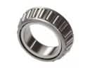 Ford Differential Bearing
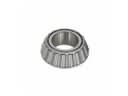 Ford Differential Pinion Bearing
 Ford Differential Seal
 Ford Driveshaft Yokes
 Ford Output Shaft Seal
 Ford Pinion Bearing
 Ford Pinion Washer
 Ford Transfer Case Shim
Browse Ford Universal Joint by Models
Ranger Bronco Mustang Explorer F-150 Escape Excursion Expedition Thunderbird Explorer Sport Trac Crown Victoria F-250 Aerostar Country Squire E-150 Econoline Explorer Sport F-350 LTD Police Interceptor Utility Tempo F-350 Super Duty LTD Crown Victoria E-150 E-150 Econoline Club Wagon E-250 E-250 Econoline E-350 Econoline E-350 Econoline Club Wagon E-350 Super Duty F-150 Heritage F-250 HD F-250 Super Duty Transit-150 Transit-250 Transit-350 Transit-350 HD