FordParts
My Garage
My Account
Cart
OEM Ford Taurus X Camshaft
Cam- Select Vehicle by Model
- Select Vehicle by VIN
Select Vehicle by Model
orMake
Model
Year
Select Vehicle by VIN
For the most accurate results, select vehicle by your VIN (Vehicle Identification Number).
6 Camshafts found


Ford Taurus X Camshaft, Passenger Side Part Number: 7T4Z-6250-C
$143.58 MSRP: $209.00You Save: $65.42 (32%)

Ford Taurus X Camshaft, Driver Side Part Number: 7T4Z-6250-B
$206.00 MSRP: $302.50You Save: $96.50 (32%)

Ford Taurus X Camshaft, Passenger Side Part Number: 7T4Z-6250-A
Ford Taurus X Camshaft, Driver Side Part Number: 7T4Z-6250-D
$180.11 MSRP: $262.17You Save: $82.06 (32%)Ford Taurus X Camshaft, Driver Side Part Number: 9T4Z-6250-B

Ford Taurus X Camshaft, Passenger Side Part Number: 9T4Z-6250-A
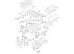
Ford Taurus X Camshaft
OEM Camshaft boasts unmatched quality. Each part goes through full quality checks. They adhere to Ford's official factory standards. These steps remove flaws and inconsistencies. So you can get Camshaft with long life and a perfect fit. Come to our website and find genuine Ford Taurus X parts. We keep a wide inventory of OEM Taurus X parts at the highly affordable prices. It's easy to search, compare, and pick what you need. You'll love the clear info and simple checkout. We offer top-rated customer service, and we reply fast. We also ship promptly to ensure your order arrives on time.
One of the intricate parts of the Ford Taurus X is the camshaft, which improvements greatly boost the Ford Taurus X, a crossover utility vehicle made by Ford from 2008 to 2009. This camshaft is in charge of controlling the intake valve and the exhaust of the engine so as to allow proper airflow and thus more power. The Camshaft is highly durable and is made of iron or steel; this makes it function in different engine types such as OHV, SOHC, and DOHC. It can be fitted to various models of Taurus X as needed, and enchances their operational efficiency and safety; this makes it suitable to drivers who want tuned up Engines. The actual control of the operations of the camshaft through the crankshaft is pivotal to the performance of the engine while other factors that are clearly illustrated as the 'higher lift and longer duration' then contributes to torque and good quality idle. More significantly, the Ford Taurus X was the first American Ford model to adopt a continuously variable transmission (CVT), which more underlines the significance of the camshaft for power-on shifting. The Camshaft is unique because of its sophisticated design and engineering; it helps to sustain a Ford stereotype of manufacturing automobiles of high quality with optimal performances. All these indicates that this camshaft has a very vital part to play in building the Ford Taurus X into a vehicle of choice by consumers.
Ford Taurus X Camshaft Parts and Q&A
- Q: How to Remove and Replace a Camshaft Safely on Ford Taurus X?A:Start the camshaft removal process by linking the Throttle Body electrical connector and the PCV hose to the PCV Valve. Once the engine and transaxle assembly reaches its proper position raise it into the vehicle through installation of three Engine Mount bolts with torque setting at 90 Nm (66 lb-ft) and after finishing the engine mount nut installation with torque setting at 63 Nm (46 lb-ft). At the next step install the engine mount brace by adding a nut and bolt before tightening them to 20 Nm (177 lb-in). Proceed to mount the transaxle support insulator bracket bolt together with three nuts which require tightening to 80 Nm (59 lb-ft) after which install the transaxle support insulator through bolt and nut to 175 Nm (129 lb-ft). The Power Transfer Unit seal must be changed with a new one when the intermediate shaft is dismounted from All-Wheel Drive vehicles. The installation of the RH halfshaft support bracket requires four bolts where the halfshaft support-to-cylinder block bolts should reach 40 Nm (30 lb-ft) torque and the Catalytic Converter-to-halfshaft support bolts should reach 20 Nm (177 lb-in torque. Install the two halfshaft support bracket studs with 10 Nm of torque (89 lb-in) and connect transaxle cooler tubes and apply two secondary latches. Employ the Powertrain Lift to raise the subframe while you install the two front subframe bolts which need to be tightened to 150 Nm (111 lb-ft). First tighten the four subframe bracket bolts finger-light before fully installing the two rear subframe bolts to 150 Nm (111 lb-ft) tension and the four subframe bracket-to-body bolts to 103 Nm (76 lb-ft). The new tie-rod end nuts require installation torque of 115 Nm (85 lb-ft) and the new upper stabilizer bar link nuts demand a torque value of 55 Nm (41 lb-ft). Fasten the two engine roll restrictor-to-transaxle bolts to a torque of 103 Nm (76 lb-ft). I will install the PSP tube onto the steering gear after I apply a new O-ring seal which requires rotating the clamp plate followed by tightening the bolt to 25 Nm (18 lb-ft) and then installing the PSP tube bracket-to-steering gear bolt at 10 Nm (89 lb-in). The engine oil filter gasket requires clean engine oil lubrication prior to new filter installation at 5 Nm (44 lb-in torque followed by 180-degree rotation step. Put the index marks of the rear driveshaft in alignment with the PTU flange before attaching four bolts that need to be tightened to 70 Nm (52 lb-ft). The installation starts with a new gasket after which the Y-pipe should be placed using fresh nuts tightened up to 40 Nm (30 lb-ft). Additionally install the exhaust hanger. Fasten the Y-pipe assembly by using new nuts at 40 Nm (30 lb-ft). Discard the intermediate shaft from rotating during disconnection which could harm the Clock Spring unless the Clock Spring needs removal for centering operations. The steering intermediate shaft needs to be installed onto the steering gear using a new bolt that requires torque to 23 Nm (17 lb-ft) and the transaxle control electrical connector must be connected followed by attaching the transaxle control wire harness to the transaxle stud bolt. Thread the hose to the Power Steering Reservoir after placing the oil level indicator into position then fasten the ground cable and bolt to 12 Nm (106 lb-in). The wire harness retainers should be installed at the RH valve cover stud bolt and engine mount bracket stud bolt before connecting both engine wiring harness electrical connectors and attaching the electrical connector to the LH valve cover. Install new O-ring seals on the A/C tube and bolt then secure them with torque to 15 Nm (133 lb-in). Proceed to connect the A/C tubes using new O-ring seals while tightening two nuts to 15 Nm (133 lb-in). The upper A/C tube needs new O-ring installation before connecting to the condenser. Then attach the nut and secure the A/C pressure switch electrical connector with 15 Nm (133 lb-in) torque. Begin by connecting the block heater wiring harness retainer to the combination of Radiator and power steering tube when such equipment is present. Use the Shift Cable bracket to connect the transaxle control cable with its control lever before attaching the Thermostat Housing components such as the upper and lower radiator hoses along with the heater hose. You should attach the Evaporative Emission tube along with the vacuum hose to the upper intake manifold as you should add the pin-type EVAP tube retainer to the upper intake manifold. The ground cable requires a 6 Nm (53 lb-in) torque setting when fastened to the negative battery terminal before the power feed wire reaches the positive battery terminal for tightening to 6 Nm (53 lb-in). The battery tray assembly installation requires tightening the nut along with bolt to 9 Nm (80 lb-in), followed by securing the two lower battery tray bracket bolts to 9 Nm (80 lb-in). Lastly, install the engine wiring harness electrical connector and connect the pin-type fasteners to the front and side of the battery tray. Fasten pin-type wiring harness holders on the battery tray at its front and side points before installing the battery and adding the engine air cleaner and air cleaner outlet pipe and finishing with the degas bottle and power steering cooler tube. Mount both LH and RH halfshafts before installing the accessory Drive Belt as well as the power steering belt. The procedure requires adding clean engine oil followed by filling up the power steering system and cooling system along with the A/C system recharge.
- Q: What precautions should be taken when removing and replacing the camshaft to prevent engine damage and ensure proper installation on Ford Taurus X?A:The camshaft replacement process requires smoking and open flames to be absent because it poses a significant risk of flammable mixture ignition. Cleanliness procedures should be followed to stop mysterious materials from causing engine breakdowns. After installing the camshafts you should check the valve clearance while maintaining the crankshaft in free wheeling position where the dowel pin points to 9 o'clock. The crankshaft should be rotated counterclockwise to reach the 9 o'clock position. Engine damage can be prevented by setting the camshafts to neutral before removal which requires clean engine oil coating prior to installation. The LH and RH cylinder heads should receive their camshafts with the bearing caps fixed in their native locations then tightened with 10 Nm (89 lb-in) torque using the specified sequence. Validate the engine valve clearance through feeler gauge measurement after installation to confirm technical specifications when new components are involved. Place the Top Dead Center (TDC) on both LH and RH camshafts before putting on the Camshaft Holding Tool to assemble Variable Camshaft Timing (VCT) components by lining the colored links with timing marks. Assemble the secondary timing components while performing a four-step bolt tightening procedure then remove lockpins from the tensioners. Follow the crankshaft clockwise rotation until it reaches TDC (dowel pin at 11 o'clock) before installing the primary timing chain that links with proper timing marks. Put in the LO LH primary timing chain guide before torquing it to 10 Nm (89 lb-in) and put in the primary timing chain tensioner arm and reset it. You should put in the primary tensioner while tightening it to 10 Nm (89 lb-in) until the lockpin becomes removable. All timing marks should be aligned before new VCT housing seals are installed as well as the VCT housing dowels are securely seated before torquing bolts to 10 Nm (89 lb-in). Put Motorcraft High Performance Engine RTV Silicone on the engine front cover sealing locations before you mount the front cover using 3 Nm (27 lb-in) torque while following bolt installation order. Proceed with installing the engine mount bracket and remaining engine front cover bolts through two stages by correctly applying thread sealer to engine mount studs. Put on the crankshaft front seal while fitting the crankshaft pulley and tighten the pulley bolt through four stages. Fitting of accessory drive belt tensioner and Power Steering Pump goes hand in hand with putting any needed new seals into place. Install RTV Silicone to engine front cover-to-cylinder head joints before fitting the RH and LH valve covers and tighten the bolts to 10 Nm (89 lb-in). Follow the installation order of PSP tube bracket, coil-on-plug assemblies and complete electrical connector reconnection. The presence of upper engine failure requires inspecting the Intake Manifold for metal debris then obtaining a new manifold if needed. To complete the installation wrap up by placing the upper intake manifold then secure all wiring harness retainers with bolts torqued up to 10 Nm (89 lb-in).


Related Ford Taurus X Parts
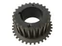 Ford Taurus X Crankshaft Gear
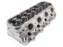 Ford Taurus X Cylinder Head
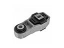 Ford Taurus X Engine Mount Torque Strut
 Ford Taurus X Harmonic Balancer
 Ford Taurus X Oil Drain Plug
 Ford Taurus X Oil Drain Plug Gasket
 Ford Taurus X Oil Pump Gasket
 Ford Taurus X Spool Valve
 Ford Taurus X Timing Chain
 Ford Taurus X Valve Cover Gasket
 Ford Taurus X Valve Stem Seal
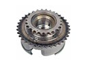 Ford Taurus X Variable Timing Sprocket