FordParts
My Garage
My Account
Cart
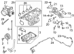
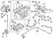
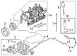
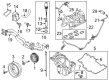
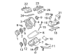
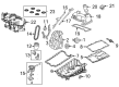
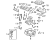
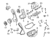
OEM Ford Ranger Intake Manifold
Engine Intake Manifold- Select Vehicle by Model
- Select Vehicle by VIN
Select Vehicle by Model
orMake
Model
Year
Select Vehicle by VIN
For the most accurate results, select vehicle by your VIN (Vehicle Identification Number).
19 Intake Manifolds found

Ford Ranger Intake Manifold Part Number: KB3Z-9424-A
$59.77 MSRP: $87.00You Save: $27.23 (32%)Ships in 1-3 Business Days
Ford Ranger Manifold Assembly - Inlet Part Number: KB3Z-9424-B
$70.65 MSRP: $102.83You Save: $32.18 (32%)Ships in 1-3 Business Days
Ford Ranger Manifold Assembly - Inlet Part Number: N2DZ-9424-D
$100.76 MSRP: $146.67You Save: $45.91 (32%)Ships in 1-2 Business Days
Ford Ranger Manifold Assembly - Inlet Part Number: ML3Z-9424-J
$101.10 MSRP: $147.17You Save: $46.07 (32%)Ships in 1-2 Business Days


Ford Ranger Intake Manifold, Upper Part Number: 4L5Z-9424-EA
$102.94 MSRP: $149.83You Save: $46.89 (32%)

Ford Ranger Intake Manifold Part Number: 4L5Z-9424-A
$377.96 MSRP: $555.00You Save: $177.04 (32%)


Ford Ranger Intake Manifold, Upper Part Number: F77Z-9424-CA


Ford Ranger Intake Manifold, Lower Part Number: F57Z-9424-D


Ford Ranger Intake Manifold Part Number: 4L5Z-9424-AJ

Ford Ranger Intake Manifold, Lower Part Number: YL5Z-9424-AA

Ford Ranger Intake Manifold, Lower Part Number: FOTZ-9424-AB

Ford Ranger Intake Manifold, Upper Part Number: F87Z-9424-HA
Ford Ranger Intake Manifold, Upper Part Number: F87Z-9424-GA

Ford Ranger Intake Manifold Part Number: F6TZ-9424-AB
Ford Ranger Intake Manifold, Upper Part Number: 98TZ-9424-CA
Ford Ranger Manifold, Upper Part Number: 7L5Z-9424-A
Ford Ranger Intake Manifold, Lower Part Number: 2L5Z-9424-EARM

Ford Ranger Intake Manifold Part Number: 1L5Z-9424-CA
Ford Ranger Intake Manifold Part Number: 1L5Z-9424-A
Ford Ranger Intake Manifold
OEM Intake Manifold boasts unmatched quality. Each part goes through full quality checks. They adhere to Ford's official factory standards. These steps remove flaws and inconsistencies. So you can get Intake Manifold with long life and a perfect fit. Come to our website and find genuine Ford Ranger parts. We keep a wide inventory of OEM Ranger parts at the highly affordable prices. It's easy to search, compare, and pick what you need. You'll love the clear info and simple checkout. We offer top-rated customer service, and we reply fast. We also ship promptly to ensure your order arrives on time.
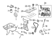
In the Ford Ranger, the Intake Manifold is responsible to directs air or air-fuel mixture to the cylinder that has a direct influence to the engine's power and torque produced by the car. It works by allowing air from the throttle body or carburetor, with differences in the kinds of engines namely carbureted, throttle body injected or multiport fuel injected. Current models of Ford Rangers use plastic' based materials such as plastic composites due to their low density and excellent heat transfer properties than the conventional cast iron or aluminum intakes. Over the years Ford Ranger vehicles have come with other features for instance Variable Length Intake Manifold (VLIM) that adjusts the intake tract length which improves the airflow and thus engine performance. Such innovations coupled with the addition of temperature and airflow sensors to the vehicles lead to enhanced combustion and efficiency of the automobile. The changes in the Intake Manifold of the Ford Ranger that will be discussed below explain the need to optimize the engine performance and its power delivery in different configurations.
Ford Ranger Intake Manifold Parts and Q&A
- Q: How to service and repair the intake manifold on Ford Ranger?A:The first step for servicing or repairing the intake manifold involves cooling system fluid drain and removing the Air Cleaner outlet pipe. The maintenance process for the Intake manifold starts by removing both Throttle Body (TB) shield bolts before disconnecting the acceleration control cable together with any speed control cable running to the intake manifold and TB. The service includes removing power connections from the Throttle Position (TP) sensor and Manifold Absolute Pressure (MAP) sensor and Idle Air Control (IAC) valve. Separately detach the engine vacuum harness and brake booster hose along with the vapor purge tube quick connect coupling and the crankcase breather hose and two coolant hoses. The two engine wiring harness pin-type retainers and the pin-type retainer located at the back of the intake manifold must be removed. Dispose of the EGR tube support bracket bolt together with the two bolts which secure the EGR tube flange. The bracket loses its fuel supply tube and electrical connectors as well as EVAP tube quick connect coupling gets disconnected. Remove the retainer from the Knock Sensor (KS) electrical connector followed by the manufacture's wiring harness pushpin from the bottom of the intake manifold and disconnect the fuel supply tube spring lock coupling. Use a plastic scraper to clean the sealing surfaces while removing previous sealant following the removal of five bolts and the intake manifold. Avoid using metal scrapers which would damage the surfaces. Securely clean the cylinder head sealing surface by applying silicone gasket remover followed by metal surface preparation treatment according to safety protocol. The replacement procedure starts with discarding the four intake manifold gaskets while inspecting the intake manifold for metal debris before a necessary replacement. The installation process involves using new gaskets for the intake manifold and then placing the manifold in position before tightening five bolts to 18 Nm (159 lb-in). Connect the wiring pushpin with KS connector retainer, electrical connectors and secure the fuel supply tube and EVAP tube quick connect coupling. Secure the two EGR flange mounting bolts and EGR tube support bracket bolt by tightening them to 18 Nm (159 lb-in). Proceed with reconnecting the engine vacuum harness alongside the brake booster hose and crankcase breather hose and two coolant hoses after positioning the engine wiring harness and connecting its two pin-type retainers. Reconnect the fuel supply tube spring lock coupling before attaching the MAP Sensor and TP sensor electrical connectors. The IAC valve electrical connector also needs reconnection. Affix the acceleration control cable to both the intake manifold and the TB while connecting the speed control cable in case of equipment presence. The last step includes attaching the TB shield and using torque up to 8 Nm (71 lb-in) for the two bolts before reinstalling the ACL outlet tube and completing the engine cooling system bleeding process.

Related Ford Ranger Parts
 Ford Ranger Fuel Pump
 Ford Ranger Fuel Filter
 Ford Ranger Fuel Tank
 Ford Ranger Mass Air Flow Sensor
 Ford Ranger Air Filter Box
 Ford Ranger Air Intake Hose
 Ford Ranger Fuel Filler Hose
 Ford Ranger Fuel Level Sensor
 Ford Ranger Intake Manifold Gasket
 Ford Ranger Air Duct
 Ford Ranger Air Intake Coupling
 Ford Ranger Fuel Pump Seal