FordParts
My Garage
My Account
Cart
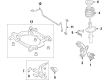
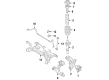
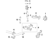
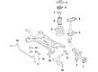
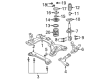
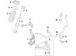
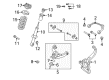
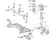
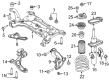
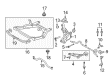
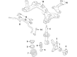
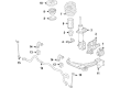
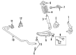
OEM Ford Steering Knuckle
Front Steering Knuckle- Select Vehicle by Model
- Select Vehicle by VIN
Select Vehicle by Model
orMake
Model
Year
Select Vehicle by VIN
For the most accurate results, select vehicle by your VIN (Vehicle Identification Number).
229 Steering Knuckles found


Ford Knuckle, Front Driver Side Part Number: BB5Z-3K186-A
$179.01 MSRP: $294.55You Save: $115.54 (40%)Ships in 1-2 Business DaysProduct Specifications- Other Name: Knuckle - Front Wheel; Steering Knuckle, Front Left
- Position: Driver Side


Ford Knuckle, Front Driver Side Part Number: CV6Z-3K186-B
$516.60 MSRP: $894.55You Save: $377.95 (43%)Product Specifications- Other Name: Knuckle - Front Wheel; Steering Knuckle, Front Left
- Position: Driver Side


Ford Knuckle, Front Driver Side Part Number: AL3Z-3K186-D
$513.56 MSRP: $852.73You Save: $339.17 (40%)Product Specifications- Other Name: Knuckle - Front Wheel; Steering Knuckle, Front Left, Left
- Position: Driver Side
- Replaces: AL3Z-3K186-A


Ford Knuckle, Front Driver Side Part Number: DV6Z-3K186-A
$277.13 MSRP: $470.91You Save: $193.78 (42%)Ships in 1-2 Business DaysProduct Specifications- Other Name: Knuckle - Front Wheel
- Position: Driver Side

Ford Knuckle, Front Passenger Side Part Number: DV6Z-3K185-A
$293.18 MSRP: $498.18You Save: $205.00 (42%)Ships in 1-2 Business DaysProduct Specifications- Other Name: Knuckle - Front Wheel
- Position: Passenger Side


Ford Knuckle, Front Driver Side Part Number: 5L8Z-3K186-BA
$221.49 MSRP: $376.36You Save: $154.87 (42%)Ships in 1-2 Business DaysProduct Specifications- Other Name: Knuckle - Front Wheel; Steering Knuckle, Front Left
- Position: Driver Side


Ford Knuckle, Front Passenger Side Part Number: HL3Z-3K185-B
$254.23 MSRP: $432.00You Save: $177.77 (42%)Ships in 1-2 Business DaysProduct Specifications- Other Name: Knuckle - Front Wheel; Steering Knuckle, Front Right
- Position: Passenger Side
- Replaces: HL3Z-3K185-A


Ford Knuckle, Front Passenger Side Part Number: FL3Z-3K185-A
$254.66 MSRP: $432.73You Save: $178.07 (42%)Ships in 1-2 Business DaysProduct Specifications- Other Name: Knuckle - Front Wheel; Steering Knuckle, Right
- Position: Front Passenger Side


Ford Knuckle, Front Driver Side Part Number: AL3Z-3K186-B
$270.71 MSRP: $460.00You Save: $189.29 (42%)Ships in 1-2 Business DaysProduct Specifications- Other Name: Knuckle - Front Wheel; Steering Knuckle, Front Left, Left
- Manufacturer Note: The Mounting Holes In New Housings Are Not Threaded.
- Position: Driver Side

Ford Knuckle, Front Passenger Side Part Number: AL3Z-3K185-B
$245.03 MSRP: $416.36You Save: $171.33 (42%)Product Specifications- Other Name: Knuckle - Front Wheel; Steering Knuckle, Front Right, Right
- Manufacturer Note: The Mounting Holes In New Housings Are Not Threaded.
- Position: Passenger Side

Ford Knuckle, Front Passenger Side Part Number: CV6Z-3K185-B
$381.19 MSRP: $652.00You Save: $270.81 (42%)Product Specifications- Other Name: Knuckle - Front Wheel; Steering Knuckle, Front Right
- Position: Passenger Side


Ford Knuckle, Front Driver Side Part Number: 2M5Z-3K186-AB
$433.70 MSRP: $741.82You Save: $308.12 (42%)Ships in 1-2 Business DaysProduct Specifications- Other Name: Knuckle - Front Wheel; Steering Knuckle, Front Left
- Manufacturer Note: L.H., (replacing YS4Z-3K185-CB), without ABS
- Position: Driver Side
- Replaces: YS4Z-3K186-CB


Ford Knuckle, Front Driver Side Part Number: BV6Z-3K186-D
$98.04 MSRP: $164.60You Save: $66.56 (41%)Ships in 1-2 Business DaysProduct Specifications- Other Name: Knuckle - Front Wheel; Steering Knuckle, Front Left
- Position: Driver Side
- Replaces: CV6Z-3K186-A, MEF-17


Ford Knuckle, Front Passenger Side Part Number: BV6Z-3K185-D
$98.04 MSRP: $164.60You Save: $66.56 (41%)Ships in 1 Business DayProduct Specifications- Other Name: Knuckle - Front Wheel; Steering Knuckle, Front Right
- Position: Passenger Side
- Replaces: CV6Z-3K185-A, MEF-16


Ford Knuckle, Front Passenger Side Part Number: BT4Z-3K185-A
$142.56 MSRP: $240.00You Save: $97.44 (41%)Ships in 1-2 Business DaysProduct Specifications- Other Name: Knuckle - Front Wheel; Steering Knuckle, Front Right
- Position: Passenger Side
- Replaces: 7T4Z-3K185-A, 7T4Z-3K185-AR


Ford Knuckle, Front Driver Side Part Number: AY1Z-3K186-A
$125.20 MSRP: $206.00You Save: $80.80 (40%)Ships in 1-2 Business DaysProduct Specifications- Other Name: Knuckle - Front Wheel; Steering Knuckle, Front Left
- Position: Driver Side


Ford Knuckle, Front Driver Side Part Number: CV6Z-3K186-C
$193.82 MSRP: $321.82You Save: $128.00 (40%)Ships in 1-2 Business DaysProduct Specifications- Other Name: Knuckle - Front Wheel; Steering Knuckle, Front Left
- Position: Driver Side


Ford Knuckle, Front Passenger Side Part Number: BB5Z-3K185-A
$179.01 MSRP: $294.55You Save: $115.54 (40%)Ships in 1-2 Business DaysProduct Specifications- Other Name: Knuckle - Front Wheel; Steering Knuckle, Front Right
- Position: Passenger Side


Ford Knuckle, Front Driver Side Part Number: F2GZ-3K186-A
$166.86 MSRP: $274.55You Save: $107.69 (40%)Ships in 1-2 Business DaysProduct Specifications- Other Name: Knuckle - Front Wheel; Steering Knuckle, Front Left
- Position: Driver Side


Ford Knuckle, Front Driver Side Part Number: GL1Z-3K186-A
$179.01 MSRP: $294.55You Save: $115.54 (40%)Ships in 1-3 Business DaysProduct Specifications- Other Name: Knuckle - Front Wheel
- Position: Driver Side
| Page 1 of 12 |Next >
1-20 of 229 Results
Ford Steering Knuckle
If you own Ford and want to keep it in top shape, choosing OEM Steering Knuckle is a smart move. They are precisely engineered and follow strict factory standards. They are made in advanced facilities that use cutting edge technology. Each part goes through thorough testing to confirm strength and safety, so you can trust it. FordPartsDeal.com gives you genuine Ford Steering Knuckle at some of the affordable online prices without cutting quality. Every OEM Ford part includes the manufacturer's warranty, easy returns, and super-fast delivery. So why wait? Shop now and get your vehicle back to peak condition.
Ford Steering Knuckle is applied to join wheel motion with steering input and maintain control that is tight and predictable. Since 1903, when Henry first laid down the initial assembly lines, Ford has pursued practical innovation, whether it be the EcoBoost engines that are squeezed to a drop or its SYNC system which lets owners holler at a choice of music or a map direction as opposed to tapping screens on the move and cutting assembly time to help cars arrive on the road faster. Performance and frugality can be compatible without drama, as its SYNC system demonstrates. Ford takes safety and clean energy equally seriously, equipping cars with Co-Pilot360 apparatus that clutches the brakes when there is danger and pushes the wheel back into the road, and driver battery trucks such as the F-150 Lightning to demonstrate that zero-emission torque can be as hard as gas-powered muscle. The Steering Knuckle keeps the suspension travel and steering angle fixed, and Ford casts the Steering Knuckle with seats to fit control arm, bearer, and tie-rod ends; therefore, pothole hits do not rattle the alignment. The Steering Knuckle jerks up on a bump on the wheel and immediately turns at a right angle as the driver turns so the Ford chassis can remain stable and attentive. Since each of the drivetrain designs alters the connections of spindles or hubs, the Steering Knuckle adapts between rear-drive sedans and all-wheel systems but continues its function of anchoring the wheel and allowing it to move freely. Easy replacement of worn stud bores or bushings in the part before they chew tires and burn bearings.
Ford Steering Knuckle Parts and Q&A
- Q: How to service and repair the steering knuckle on Ford Expedition?A:You must begin servicing or repairing the steering knuckle by removing wheel hubs combined with initial adjustment marks on both torsion bars and torsion bar crossmember supports followed by length measurement and recording. Start by using the Torsion Bar Tool along with the Torsion Bar Tool Adapters in the B slots to relieve torsion bar tension. After tightening the tool until the adjuster nut becomes free the tool can be removed together with the adjuster nut. Start by securely moving the anti-lock sensor wire by unbolt its anchor point. The first step is to discard the cotter pin to access the tie rod end castle nut followed by using a Pitman Arm Puller to disassemble the tie rod end from the front wheel knuckle. Perform the sequence starting with front suspension lower arm removal of its shock absorber lower bolt and nut followed by upper ball joint castle nut stripping which necessitates a Pitman Arm Puller to detach the front wheel knuckle from front suspension upper arm. To remove the front suspension lower arm from the front wheel knuckle you must first discard the cotter pin from the lower ball joint castle nut before using the Pitman Arm Puller. The front wheel driveshaft and joint must receive wire support to keep them safe while the front wheel knuckle is being uninstalled. Position the front wheel knuckle and secure it by installing the front suspension arm lower ball joint castle nut while using a new cotter pin for attachment. First establish the upper ball joint castle nut then proceed to install the front shock absorber lower bolt combined with its nut to the front suspension lower arm. First install the tie rod end castle nut with a new cotter pin while positioning it correctly afterward position the anti-lock sensor wire before securing it with the bracket bolt. To properly load the torsion bar operate the adjuster nut until reference marks match before installing the tool with the adapters and tightening it sufficiently to load the bar then add the adjuster components before you remove the tool. After installation of the wheel hub finish height adjustment procedures.
- Q: How to Service and Repair the Front Steering Knuckle on Ford Thunderbird?A:You should start service or repair of the front wheel knuckle by removing both the wheel bearing and hub component. Apply the hex-holding feature to stop stud rotation and unscrew thetie-rod end nut followed by disconnecting the tie-rod end from the wheel knuckle after you tighten the new nut to 100 Nm (74 ft. lbs.). The weight of the knuckle should be held by a suitable jack stand when the lower control arm becomes disconnected to protect the upper control arm. Disconnect the suspension lower arm from the knuckle by removing and discarding the lower ball joint-to-lower arm nut and tighten the new nut to 200 Nm (148 ft. lbs.) when installing. The hex-holding feature should be activated before removing the nut to stop stud rotation and the original tapered ball joint washer must be placed over the new nut. When working on the knuckle support it through elevation to avoid damaging the upper control arm. Use new nuts when reinstalling the arm-to-knuckle connections for both upper and lower segments of the arm and tie rod section together with the tapered washer positioned on ball joints before reassembly according to reverse installation steps, torque the knuckle joints to 90 Nm (66 ft. lbs.).


Related Ford Parts
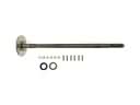 Ford Axle Shaft
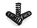 Ford Coil Springs
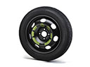 Ford Spare Wheel
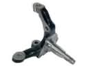 Ford Spindle
 Ford Trailing Arm
 Ford Coil Spring Insulator
 Ford Lateral Link
 Ford Strut Housing
 Ford Strut Mounts
 Ford Suspension Control Module
 Ford Sway Bar Bushing
 Ford Wheel Stud
Browse Ford Steering Knuckle by Models
Ranger Bronco Mustang Explorer Focus Fusion F-150 Maverick EXP Escape Edge Excursion Expedition Fiesta Taurus Thunderbird Flex Transit Connect Bronco Sport Explorer Sport Trac Crown Victoria EcoSport Escort F-250 C-Max Contour Explorer Sport F-350 Five Hundred Freestar Freestyle Mustang Mach-E Police Interceptor Utility Taurus X Tempo Windstar F-350 Super Duty Police Interceptor Sedan E-150 E-250 E-250 Econoline E-350 Club Wagon E-350 Econoline E-350 Econoline Club Wagon E-350 Super Duty E-Transit F-150 Heritage F-150 Lightning F-250 HD F-250 Super Duty Police Responder Hybrid Special Service Police Sedan SSV Plug-In Hybrid Transit-150 Transit-250 Transit-350 Transit-350 HD