FordParts
My Garage
My Account
Cart
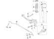
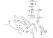
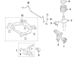
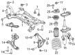
OEM Ford Coil Springs
Strut Spring- Select Vehicle by Model
- Select Vehicle by VIN
Select Vehicle by Model
orMake
Model
Year
Select Vehicle by VIN
For the most accurate results, select vehicle by your VIN (Vehicle Identification Number).
895 Coil Springs found


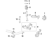
Ford Coil Spring, Front Part Number: BL3Z-5310-A
$184.35 MSRP: $268.33You Save: $83.98 (32%)Ships in 1-3 Business DaysProduct Specifications- Other Name: Spring - Front; Coil Spring, Front; Coil Springs; Spring
- Position: Front


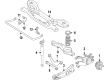
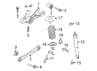
Ford Coil Spring, Rear Part Number: CV6Z-5560-N
$57.24 MSRP: $94.18You Save: $36.94 (40%)Product Specifications- Other Name: Spring - Rear; Coil Spring, Rear; Coil Springs; Spring
- Position: Rear
- Replaces: CV6Z-5560-J


Ford Coil Spring, Rear Part Number: CV6Z-5560-G
$111.61 MSRP: $183.64You Save: $72.03 (40%)Ships in 1-3 Business DaysProduct Specifications- Other Name: Spring - Rear; Coil Spring, Rear; Coil Springs; Spring
- Position: Rear


Ford Coil Spring, Rear Part Number: CV6Z-5560-E
$111.61 MSRP: $183.64You Save: $72.03 (40%)Ships in 1-3 Business DaysProduct Specifications- Other Name: Spring - Rear; Coil Spring, Rear; Coil Springs; Spring
- Position: Rear


Ford Coil Spring, Rear Part Number: CV6Z-5560-L
$112.71 MSRP: $185.45You Save: $72.74 (40%)Ships in 1-3 Business DaysProduct Specifications- Other Name: Spring - Rear; Coil Spring, Rear; Coil Springs; Spring
- Position: Rear


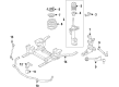
Ford Coil Spring, Purple/White, Front Part Number: DV6Z-5310-D
$77.54 MSRP: $119.33You Save: $41.79 (36%)Ships in 1-3 Business DaysProduct Specifications- Other Name: Spring - Front; Coil Spring, Front; Coil Springs; Spring
- Manufacturer Note: Purple / White / Purple
- Position: Front


Ford Coil Spring, Front Part Number: DB5Z-5310-G
$87.40 MSRP: $134.50You Save: $47.10 (36%)Ships in 1-2 Business DaysProduct Specifications- Other Name: Spring - Front; Coil Spring, Front; Coil Springs; Spring
- Position: Front
- Replaces: DB5Z-5310-D, BB5Z-5310-A


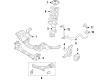
Ford Coil Spring, Front Part Number: 9L1Z-5310-Q
$130.68 MSRP: $201.67You Save: $70.99 (36%)Ships in 1-3 Business DaysProduct Specifications- Other Name: Spring - Front; Coil Spring, Front; Coil Springs; Spring
- Position: Front
- Replaces: 7L7Z-5310-K, 9L1Z-5310-K


Ford Coil Spring, Front Part Number: 1W6Z-5310-AA
$687.38 MSRP: $1018.33You Save: $330.95 (33%)Ships in 1-3 Business DaysProduct Specifications- Other Name: Spring - Front; Coil Spring, Front; Coil Springs; Spring
- Position: Front


Ford Coil Spring, Front Part Number: DV6Z-5310-C
$59.54 MSRP: $86.67You Save: $27.13 (32%)Ships in 1-2 Business DaysProduct Specifications- Other Name: Spring - Front; Coil Spring, Front; Coil Springs; Spring
- Manufacturer Note: RH/LH
- Position: Front


Ford Coil Spring, Front Part Number: CV6Z-5310-Q
$60.00 MSRP: $87.33You Save: $27.33 (32%)Product Specifications- Other Name: Spring - Front; Coil Spring, Front; Coil Springs; Spring
- Position: Front


Ford Coil Spring, Front Part Number: CV6Z-5310-N
$60.23 MSRP: $87.67You Save: $27.44 (32%)Product Specifications- Other Name: Spring - Front; Coil Springs; Spring
- Position: Front

Ford Coil Spring, Front Part Number: DV6Z-5310-H
$61.94 MSRP: $90.17You Save: $28.23 (32%)Ships in 1-3 Business DaysProduct Specifications- Other Name: Spring - Front; Coil Spring, Front; Coil Springs; Spring
- Manufacturer Note: RH/LH
- Position: Front
- Replaces: DV6Z-5310-B


Ford Coil Spring, Rear Part Number: BR3Z-5560-C
$65.95 MSRP: $96.00You Save: $30.05 (32%)Ships in 1-3 Business DaysProduct Specifications- Other Name: Spring - Rear; Coil Spring, Rear; Coil Springs; Spring
- Position: Rear


Ford Coil Spring, Front Part Number: FR3Z-5310-X
$73.74 MSRP: $107.33You Save: $33.59 (32%)Ships in 1-3 Business DaysProduct Specifications- Other Name: Spring - Front; Coil Spring, Front; Coil Springs; Spring
- Manufacturer Note: RH/LH
- Position: Front
- Replaces: FR3Z-5310-L


Ford Coil Spring, Front Part Number: BR3Z-5310-A
$73.85 MSRP: $107.50You Save: $33.65 (32%)Ships in 1-3 Business DaysProduct Specifications- Other Name: Spring - Front; Coil Spring, Front; Coil Springs; Spring
- Position: Front

Ford Coil Spring, Front Part Number: DB5Z-5310-K
$79.23 MSRP: $115.33You Save: $36.10 (32%)Ships in 1-3 Business DaysProduct Specifications- Other Name: Spring - Front; Coil Spring, Front; Coil Springs; Spring
- Position: Front
- Replaces: DB5Z-5310-F

Ford Coil Spring, Front Part Number: FR3Z-5310-M
$80.61 MSRP: $117.33You Save: $36.72 (32%)Ships in 1-2 Business DaysProduct Specifications- Other Name: Spring - Front; Coil Spring, Front; Coil Springs; Spring
- Manufacturer Note: RH/LH
- Position: Front


Ford Coil Spring, Front Part Number: BB5Z-5310-D
$87.82 MSRP: $127.83You Save: $40.01 (32%)Ships in 1-3 Business DaysProduct Specifications- Other Name: Spring - Front; Coil Spring, Front; Coil Springs; Spring
- Position: Front
- Replaces: BB5Z-5310-B


Ford Coil Spring, Front Part Number: F2GZ-5310-A
$102.71 MSRP: $149.50You Save: $46.79 (32%)Ships in 1-3 Business DaysProduct Specifications- Other Name: Spring - Front; Coil Spring, Front; Coil Springs; Spring
- Manufacturer Note: RH/LH
- Position: Front
| Page 1 of 45 |Next >
1-20 of 895 Results
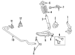
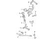
Ford Coil Springs
If you own Ford and want to keep it in top shape, choosing OEM Coil Springs is a smart move. They are precisely engineered and follow strict factory standards. They are made in advanced facilities that use cutting edge technology. Each part goes through thorough testing to confirm strength and safety, so you can trust it. FordPartsDeal.com gives you genuine Ford Coil Springs at some of the affordable online prices without cutting quality. Every OEM Ford part includes the manufacturer's warranty, easy returns, and super-fast delivery. So why wait? Shop now and get your vehicle back to peak condition.
The Ford Coil Springs absorb the bumps and maintain all levels of the ride to ensure that the drivers are comfortable and in control. Ford has pursued practical innovation since 1903, whether it was the moving assembly line that cut production time by half or the EcoBoost engines which combine eye-catching acceleration with pocket-friendly fuel economy for the everyday driver. Ford now combines SYNC voice control with integrated infotainment, allowing teenagers to switch songs or navigate without using the touch of a finger on the wheel even during gridlock traffic. Co-Pilot360 tools are ready to assist with activating fast automatic braking and constant lane control, which proves that Ford does not prioritize flashy gimmicks when it comes to a high-speed highway run at the end of the night. The battery-powered pickups which leave tailpipes cold are also rolled out by the company and this indicates that Ford can combine workhorse torque with zero exhaust on the daily commute while remaining quiet. Coil Springs struggle to sag when the road becomes cracked or curvy to maintain ride height, washing tires away in odd ways and securing cabin balance. Linear Coil Springs provide predictable support and progressive alternatives get firmer as they compress, thus steering will remain composed with a light load or heavy load. Coil Springs are fitted at both axles to distribute the weight over the chassis and absorb inappropriate jolts, which provides sharper handling and spares passengers from head-bobbing. The Coil Springs are durable steel and smart stroke tuned to absorb years of potholes, towing work, and weekend trails without falling out of their confident stride.
Ford Coil Springs Parts and Q&A
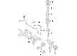
- Q: How to remove and install the coil springs and shock absorber on 4WD Ford Bronco II?A:To remove and instal the spring abd shock absorber the following procedure needs to be followed, safely lifts the car body by using the jack and put the jack stands under the frame of the car, then put the jack under the axle and position it over the spring to compress the spring. Subsequently, unbolt the shock and take out the nut given to the center of the shock absorber to the radius arm and pull the shock from the stud. Next remove the nut which locks the spring to the axle and the radius arm and then the retainer. Slowly level the axle so all the spring forces are off as to create enough room to take the spring out of its place. Take out the spacer and the seat and retain the upper coil from the tabs in the upper spring seat then turn it anti-clockwise to be released. If required screw the stud on the axle and then tighten it to 190-230 ft. lbs. If the left is applicated, then put the lower seat and spacer on the stud. Place the spring and gradually raise the front axle, and make certain that both the springs are securely mounted in the upper spring pockets. After that, place the spring lower retainer on the stud and the lower seat and tighten the attaching nut to 70- 100 ft. lbs. Last but not the least fix the shock absorser on the lower stud and fit the nut and make the torque of 41-63 ft lbs. , and then lower the vehicle.

Related Ford Parts
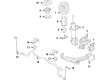
 Ford Axle Pivot Bushing
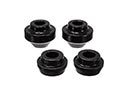 Ford Radius Arm Bushing
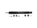 Ford Shock Absorber
 Ford Spare Wheel
 Ford Axle Vent
 Ford Bump Stop
 Ford Control Arm Bolt
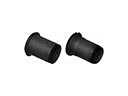 Ford Control Arm Bushing
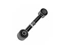 Ford Lateral Link
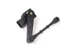 Ford Ride Height Sensor
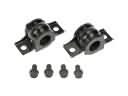 Ford Sway Bar Bracket
 Ford Trailing Arm Bushing
Browse Ford Coil Springs by Models
Ranger Bronco Mustang Explorer Focus Fusion F-150 Maverick Escape Edge Excursion Expedition Fiesta Taurus Thunderbird Flex Transit Connect Bronco Sport Explorer Sport Trac Crown Victoria Probe Bronco II EcoSport Escort F-250 Aerostar Aspire C-Max Contour Country Squire E-150 Econoline Five Hundred Freestar Freestyle LTD Mustang Mach-E Police Interceptor Utility Taurus X Windstar F-350 Super Duty LTD Crown Victoria Police Interceptor Sedan E-150 E-150 Club Wagon E-150 Econoline Club Wagon E-250 E-250 Econoline E-350 Club Wagon E-350 Econoline E-350 Econoline Club Wagon E-350 Super Duty E-Transit F-150 Heritage F-150 Lightning F-250 HD F-250 Super Duty Police Responder Hybrid Special Service Police Sedan SSV Plug-In Hybrid Transit-150 Transit-250 Transit-350 Transit-350 HD