FordParts
My Garage
My Account
Cart
OEM Lincoln Front Cross-Member
Front Engine Cross Member- Select Vehicle by Model
- Select Vehicle by VIN
Select Vehicle by Model
orMake
Model
Year
Select Vehicle by VIN
For the most accurate results, select vehicle by your VIN (Vehicle Identification Number).
94 Front Cross-Members found

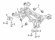
Lincoln Suspension Crossmember Part Number: NC5Z-5C145-A
$541.54 MSRP: $1120.63You Save: $579.09 (52%)Ships in 1-2 Business DaysProduct Specifications- Other Name: Frame Assembly; Crossmember
- Replaced by: TC5Z-5C145-A

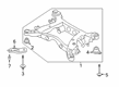
Lincoln Suspension Crossmember, Rear Part Number: HG9Z-5035-A
$393.34 MSRP: $616.72You Save: $223.38 (37%)Ships in 1-2 Business DaysProduct Specifications- Other Name: Cross Member Assembly; Suspension Subframe Crossmember, Rear; Crossmember
- Position: Rear
- Replaces: DG9Z-5035-A, DG9Z-5035-C

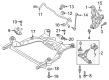
Lincoln Front Crossmember Part Number: DT4Z-5019-A
$98.60 MSRP: $151.73You Save: $53.13 (36%)Ships in 1 Business DayProduct Specifications- Other Name: Cross Member Assembly; Suspension Subframe Crossmember, Front; Crossmember
- Manufacturer Note: Includes RH And LH Sides
- Position: Front

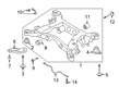
Lincoln Suspension Crossmember Part Number: MB5Z-5035-G
$636.87 MSRP: $943.52You Save: $306.65 (33%)Ships in 1-2 Business DaysProduct Specifications- Other Name: Cross Member Assembly; Crossmember
- Replaces: MB5Z-5035-A, MB5Z-5035-E

Lincoln Engine Cradle Part Number: K2GZ-5C145-A
$553.57 MSRP: $820.10You Save: $266.53 (33%)Ships in 1-3 Business DaysProduct Specifications- Other Name: Frame Assembly; Crossmember
- Replaces: F2GZ-5C145-E

Lincoln Engine Cradle, Front Part Number: K2GZ-5C145-B
$568.59 MSRP: $842.35You Save: $273.76 (33%)Ships in 1-3 Business DaysProduct Specifications- Other Name: Frame Assembly; Suspension Subframe Crossmember, Front; Crossmember
- Position: Front
- Replaces: F2GZ-5C145-D, F2GZ-5C145-R, F2GZ-5C145-B, F2GZ-5C145-L, F2GZ-5C145-F

Lincoln Suspension Crossmember Part Number: KA1Z-5035-A
$586.02 MSRP: $868.18You Save: $282.16 (33%)Ships in 1-3 Business DaysProduct Specifications- Other Name: Cross Member Assembly; Crossmember

Lincoln Suspension Crossmember, Rear Part Number: F2GZ-5035-H
$588.72 MSRP: $872.18You Save: $283.46 (33%)Ships in 1-3 Business DaysProduct Specifications- Other Name: Cross Member Assembly; Suspension Subframe Crossmember, Rear; Crossmember
- Position: Rear
- Replaces: F2GZ-5035-B, F2GZ-5035-C, F2GZ-5035-G
Lincoln Suspension Crossmember Part Number: NC5Z-5C145-B
$632.72 MSRP: $937.37You Save: $304.65 (33%)Ships in 1-2 Business DaysProduct Specifications- Other Name: Frame Assembly; Crossmember
- Replaces: LC5Z-5C145-C

Lincoln Suspension Crossmember Part Number: KA1Z-5035-B
$655.64 MSRP: $971.32You Save: $315.68 (33%)Ships in 1-3 Business DaysProduct Specifications- Other Name: Cross Member Assembly; Crossmember

Lincoln Suspension Crossmember Part Number: MC5Z-5035-E
$776.48 MSRP: $1150.33You Save: $373.85 (33%)Ships in 1-2 Business DaysProduct Specifications- Other Name: Cross Member Assembly; Crossmember
- Replaces: MC5Z-5035-B

Lincoln Engine Cradle Part Number: HG9Z-5C145-B
$837.55 MSRP: $1240.82You Save: $403.27 (33%)Ships in 1-3 Business DaysProduct Specifications- Other Name: Frame Assembly; Crossmember

Lincoln Suspension Crossmember Part Number: LX6Z-5035-AF
$889.09 MSRP: $1317.17You Save: $428.08 (33%)Ships in 1-2 Business DaysProduct Specifications- Other Name: Cross Member Assembly; Crossmember
- Replaces: LX6Z-5035-U
Lincoln Suspension Crossmember Part Number: LX6Z-5035-AE
$930.24 MSRP: $1378.13You Save: $447.89 (33%)Ships in 1-2 Business DaysProduct Specifications- Other Name: Cross Member Assembly; Crossmember
- Replaces: LX6Z-5035-V

Lincoln Frame Assembly Part Number: FL1Z-5005-E
$2975.14 MSRP: $4407.62You Save: $1432.48 (33%)Ships in 1-3 Business DaysProduct Specifications- Other Name: Frame Rail
- Replaces: 7L1Z-5005-E, 7L1Z-5005-JC, AL1Z-5005-A, EL1Z-5005-A, 9L1Z-5005-AC, FL1Z-5005-A


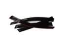
Lincoln Repair Kit Part Number: 9L3Z-5025-A
$80.77 MSRP: $117.57You Save: $36.80 (32%)Product Specifications- Other Name: Crossmember; Frame Crossmember


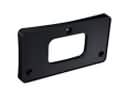
Lincoln Front Crossmember Part Number: 3W1Z-5019-AA
$22.91 MSRP: $32.50You Save: $9.59 (30%)Product Specifications- Other Name: Cross Member Assembly; Frame Crossmember, Front
- Position: Front

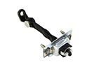
Lincoln Transmission Support Part Number: FOAZ-5027-A
Product Specifications- Other Name: Crossmember; Transfer Case Mount; Transmission Mount; Trans Crossmember


Lincoln Crossmember Part Number: F8AZ-5019-AA
Product Specifications- Other Name: Cross Member Assembly


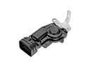
Lincoln Transmission Support Part Number: 3W1Z-5027-AA
Product Specifications- Other Name: Crossmember; Transmission Crossmember; Transfer Case Mount; Transmission Mount; Trans Crossmember
| Page 1 of 5 |Next >
1-20 of 94 Results
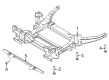
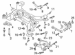
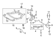
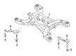
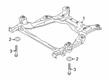
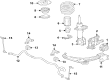
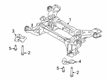
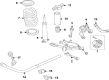
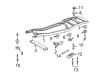
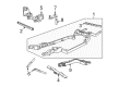
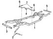
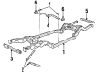
Lincoln Front Cross-Member
If you own Lincoln and want to keep it in top shape, choosing OEM Front Cross-Member is a smart move. They are precisely engineered and follow strict factory standards. They are made in advanced facilities that use cutting edge technology. Each part goes through thorough testing to confirm strength and safety, so you can trust it. FordPartsDeal.com gives you genuine Lincoln Front Cross-Member at some of the affordable online prices without cutting quality. Every OEM Lincoln part includes the manufacturer's warranty, easy returns, and super-fast delivery. So why wait? Shop now and get your vehicle back to peak condition.
Lincoln Front Cross-Member secures the engine bay to ensure that the entire car becomes tighter around every turn. Lincoln is the champion of Quiet Flight, which has reduced the noise in the cabin to remain silent at highway speed. Cushy seats, bright displays and regular technology refresh make the line-up feel new to new customers. Lincoln also includes ActiveGlide to enable the use of the car for true hands-free cruise on mapped highways, which makes long drives easy. Co-Pilot360 integrates lane keeping, auto high beams, and blind spots into a single amiable toolkit. The company is responsive to owners' feedback and acts fast, throwing away gimmicks and investing in what drivers want. Lincoln has a low and wide mounting of the Front Cross-Member under the engine that binds the frame rails together, thus preventing flex in cornering. The Front Cross-Member supports the transmission mount and maintains pickup points of the suspension in line, making steering straight on uneven pavement. The Front Cross-Member is constructed of high-grade steel and absorbs torsion that would otherwise shake body panels and reduce the life of components. Crash strength and Lincoln ride quality can be restored in a few minutes when the weakened Front Cross-Member is substituted back.
Lincoln Front Cross-Member Parts and Q&A
- Q: How to Service and Repair the Front Cross-Member on Lincoln LS?A:Start the front crossmember service and repair process by taking out the upper radiator sight shield followed by hanging the radiator to the upper radiator support. The first step includes fitting the three-bar engine support before removing the front wheel assemblies with their attached tires. The procedure requires you to first remove the eight bolts in combination with two front I-braces and discard the bolts. First detach the two clips then move away the front anti-lock brake sensors before using a tool to remove the four bolts which will facilitate front brake caliper positioning aside. It is important to grip the external hex of tie rods when removing their two nuts as part of the separation process to detach tie rod ends from the front spindles. The external hex on stabilizer bar links requires holding during the process of removing and throwing away the two nuts which separate the links from the lower control arm. Both of these steps require keeping firm control of the external hex on ball joints before you discard the nuts which will split the upper ball joint from its attachment on the spindle. Start by removing the underbody splash shields then unfasten the A/C and power steering line bracket bolts while keeping in mind the nut has better access from above the front of the radiator support crossmember. You should loosen the dust cap nut two turns, remove the bolt and place the water control valve aside specifically for the 3.9L version. Position and support the power steering gear aside by detaching the block heater harness retainer followed by the bolts. Discard the nuts during this process. The next step involves removing engine mount nuts as well as lower front strut mount bolts while securing the front crossmembers to the lift table because this step can be dangerous without adequate support. First indicate the body positions for right and left crossmembers on the assembly before setting the lifting table below these points and removing four engine crossmember bolts and four radiator support crossmember bolts. To begin the operation remove the control arm nuts and bolts followed by their removal. The radiator support crossmember removal requires the removal of its bolts as well as the water control valve bracket along with discarding the bolts and setting the stabilizer bar to the side. First install the stabilizer bar before adding new bolts then put in the water control valve bracket using its corresponding bolts. You should install the new control arm cam bolts and nuts while keeping them loose before placing the assembled radiator support and engine crossmember section together with correct crossmember markings and no engine weight contact before bolting everything tight. Begin by installing the four crossmember bolts situated below the engine and the four crossmember bolts attached to the radiator support bracket. Afterward you should install the engine mount nuts together with the new lower front strut mount bolts. Strategy #2 should be followed when torqueing the new nuts but this time on the ball joint external hex and with the ball joints in the spindles. After caution for stabilizer bar links you must install the power steering gear and its bolts. Install new nuts by holding the external hex of the tie rods before placing both tie rod ends into the spindles. Install first the two front brake calipers before securing their bolts and afterward position the two front anti-lock brake sensors with their clips for 3.9L model vehicles. After installing the block heater harness the technician should place the water control valve while tightening the nut on it. Start by placing A/C and power steering brackets then bolt them into their proper position. After that position two front I-braces loosely while installing four bolts. Check that front I-brace insulators sit correctly before securing the bolts. Complete the installation by adding underbody splash shields followed by wheel and tire components then remove the three-bar engine support before taking off radiator support while installing the upper radiator sight shield with proper front suspension alignment.
- Q: How to service and repair the front cross-member of the transmission support on Lincoln Town Car?A:The transmission support crossmember requires servicing after a vehicle positions on a hoist with its transmission set in neutral gear. Separate the right-hand (RH) HO2S sensor connector while also disconnecting the catalyst monitor connector before deleting the bolts attached to the RH exhaust flange. Starting from the exhaust clamp release then detach the RH exhaust pipe. Proceed with LH side service by unscrewing LH exhaust pipe bolts from the exhaust flange then loosen the exhaust clamp before removing the LH exhaust pipe. Start by dislodging the nuts from the rear transmission insulator followed by installation of an appropriate transmission jack. Disassemble the parking brake cable bracket by removing its securing bolts before setting it aside and then remove the bolts from the RH and LH side crossmember system followed by the crossmember bolts. You must gently pry the crossmember out from its pocket because it fits using press methods; start with lowering the RH side initially and next remove the LH side so extract the crossmember. Start by placing the left-hand crossmember section into its pocket on the transmission and loosely install the two bolts followed by performing the same steps on the right-hand crossmember section. You must start by tightening the bolts on both the LH and RH crossmember then reinstall the parking brake cable bracket. After that lower the transmission onto the crossmember and install the rear transmission insulator nuts before removing the transmission jack. Install the RH catalytic converter assembly without coping with the clamp before installing and tightening the RH exhaust flange nuts and setting the right clamp tension. Proceed to attach connectors of the RH HO2S sensor and catalyst monitor and then place the LH catalytic converter assembly into position before securing the LH exhaust flange nuts and tightening the LH exhaust clamp. The final step requires cable connection of the HO2S sensor and catalyst monitor before putting down the vehicle.