FordParts
My Garage
My Account
Cart
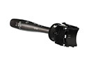
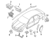
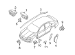
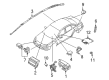
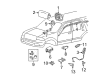
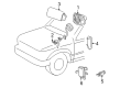
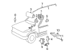
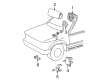
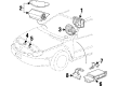
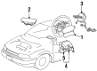
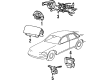
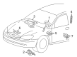
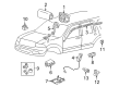
OEM Mercury Clock Spring
Spiral Cable Clock Spring- Select Vehicle by Model
- Select Vehicle by VIN
Select Vehicle by Model
orMake
Model
Year
Select Vehicle by VIN
For the most accurate results, select vehicle by your VIN (Vehicle Identification Number).
39 Clock Springs found


Mercury Clockspring Part Number: 8L8Z-14A664-A
$130.13 MSRP: $200.82You Save: $70.69 (36%)Ships in 1-3 Business DaysProduct Specifications- Other Name: Cover And Contact Plate Assembly; Air Bag Clockspring


Mercury Clockspring Part Number: 6W1Z-14A664-A
$97.91 MSRP: $142.52You Save: $44.61 (32%)Product Specifications- Other Name: Cover And Contact Plate Assembly; Air Bag Clockspring
- Manufacturer Note: AFTER 05/23/06
- Replaces: 5W1Z-14A664-AA


Mercury Clockspring Part Number: BE5Z-14A664-A
$100.08 MSRP: $145.68You Save: $45.60 (32%)Product Specifications- Other Name: Cover And Contact Plate Assembly; Air Bag Clockspring
- Replaces: 6E5Z-14A664-B, 8E5Z-14A664-A


Mercury Clockspring Part Number: BE5Z-14A664-B
$105.15 MSRP: $153.05You Save: $47.90 (32%)Product Specifications- Other Name: Cover And Contact Plate Assembly; Air Bag Clockspring
- Replaces: 9E5Z-14A664-A


Mercury Clockspring Part Number: 8G1Z-14A664-A
$108.95 MSRP: $158.58You Save: $49.63 (32%)Product Specifications- Other Name: Cover And Contact Plate Assembly; Air Bag Clockspring


Mercury Clockspring Part Number: 8L2Z-14A664-B
$181.35 MSRP: $263.97You Save: $82.62 (32%)Product Specifications- Other Name: Cover And Contact Plate Assembly; Air Bag Clockspring
- Replaces: 6L2Z-14A664-A


Mercury Clockspring Part Number: F87Z-14A664-CC
$237.35 MSRP: $348.53You Save: $111.18 (32%)Ships in 1-3 Business DaysProduct Specifications- Other Name: Cover And Contact Plate Assembly; Air Bag Clockspring
- Replaces: F87Z-14A664-HA, F87Z-14A664-CA, F87Z-14A664-CB

Mercury Clockspring Part Number: 5L8Z-14A664-AB
$166.33 MSRP: $256.68You Save: $90.35 (36%)Ships in 1-3 Business DaysProduct Specifications- Other Name: Cover And Contact Plate Assembly; Air Bag Clockspring
- Replaces: 5L8Z-14A664-AA

Mercury Clockspring Part Number: F87Z-14A664-EC
$387.08 MSRP: $535.49You Save: $148.41 (28%)Ships in 1-2 Business DaysProduct Specifications- Other Name: Cover And Contact Plate Assembly; Air Bag Clockspring
- Manufacturer Note: w/steering wheel mounted audio controls, FROM 2/16/98
- Replaces: F87Z-14A664-EA, F87Z-14A664-EB


Mercury Clockspring Part Number: F7AZ-14A664-BA
Product Specifications- Other Name: Cover And Contact Plate Assembly; Air Bag Clockspring
- Manufacturer Note: #F7AC 14A664-AA, BA - snap on type, retaining screws not required, FROM 5/97
- Replaces: F7AZ-14A664-AA


Mercury Clockspring Part Number: 5F9Z-14A664-AA
Product Specifications- Other Name: Cover And Contact Plate Assembly; Air Bag Clockspring


Mercury Clockspring Part Number: 1W1Z-14A664-AA
$214.42 MSRP: $314.87You Save: $100.45 (32%)Product Specifications- Other Name: Cover And Contact Plate Assembly; Air Bag Clockspring


Mercury Clockspring Part Number: 5F2Z-14A664-AA
$278.68 MSRP: $409.22You Save: $130.54 (32%)Product Specifications- Other Name: Cover And Contact Plate Assembly; Air Bag Clockspring
- Replaces: 3F2Z-14A664-AA


Mercury Clockspring Part Number: 1W7Z-14A664-AA
$447.49 MSRP: $657.10You Save: $209.61 (32%)Product Specifications- Other Name: Cover And Contact Plate Assembly; Air Bag Clockspring
- Manufacturer Note: without redundant steering wheel controls

Mercury Clockspring Part Number: XF5Z-14A664-BA
Product Specifications- Other Name: Cover And Contact Plate; Air Bag Clockspring; Cover And Contact Plate Assembly
- Manufacturer Note: Kit: includes contact,att. parts IS sheet
- Replaces: XF5Z-14A664-AB


Mercury Clockspring Part Number: F8AZ-14A664-AA
Product Specifications- Other Name: Cover And Contact Plate Assembly; Air Bag Clockspring
- Manufacturer Note: #F8AC 14A664-AA, screw-mounted


Mercury Clockspring Part Number: F87Z-14A664-DB
Product Specifications- Other Name: Cover And Contact Plate Assembly; Air Bag Clockspring
- Replaces: F87Z-14A664-DA


Mercury Clockspring Part Number: 8L3Z-14A664-A
Product Specifications- Other Name: Cover And Contact Plate Assembly; Air Bag Clockspring
- Replaces: 2L2Z-14A664-AB, 7L3Z-14A664-A


Mercury Clockspring Part Number: 4F1Z-14A664-AB
Product Specifications- Other Name: Cover And Contact Plate Assembly; Air Bag Clockspring
- Manufacturer Note: Atlanta and Chicago built, AFTER 12/17/03
- Replaces: 4F1Z-14A664-AA


Mercury Clockspring Part Number: 1L2Z-14A664-AB
Product Specifications- Other Name: Cover And Contact Plate Assembly; Air Bag Clockspring
| Page 1 of 2 |Next >
1-20 of 39 Results
Mercury Clock Spring
If you own Mercury and want to keep it in top shape, choosing OEM Clock Spring is a smart move. They are precisely engineered and follow strict factory standards. They are made in advanced facilities that use cutting edge technology. Each part goes through thorough testing to confirm strength and safety, so you can trust it. FordPartsDeal.com gives you genuine Mercury Clock Spring at some of the affordable online prices without cutting quality. Every OEM Mercury part includes the manufacturer's warranty, easy returns, and super-fast delivery. So why wait? Shop now and get your vehicle back to peak condition.
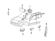
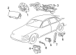
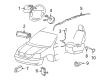
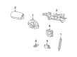
Mercury Clock Spring retains steering-wheel airbags in a wired condition, even in hard-cranking corners. In 1939, Mercury was named after the fleet-footed Roman deity and since that time, it had a name that gave it a sense of style as well as a ride that was comfortable with drivers having a sense that midsize of the road need not be the middle of that road. Mercury continued to fiddle with suspensions, silence road noise, and add value, so our customers got a badge that they could drive easy rather than admire, a badge that remained focused on day-to-day comfort until production ceased in 2011. The Clock Spring, which is a ribbon cable, has been coiled up inside the steering column and the wheel turns several full turns, even as steady current flows to the airbag and horn; Mercury uses durable conductors, and tight winding tolerances have been applied, such that the impact sensors can speak immediately rather than wait for a chance. Clock Spring is self-rewinding per rotation, which removes frayed wire and keeps cruise control buttons alive on long trips when making daily trips. The drivers are confident with the Clock Spring as the sealed casing prevents dust and moisture which may slice the circuit. Upon impact of collisions, the unbroken route of the Clock Spring allows the fire of the airbags to be made within milliseconds without delay.
Mercury Clock Spring Parts and Q&A
- Q: How to Safely and Effectively Service the Clock Spring on Mercury Cougar?A:Safety must be established before working on the air bag sliding contact by waiting a minimum of one minute after disconnecting the battery cables before touching any supplemental restraint system electrical connectors and electronic air bag control module. Safety glasses must be worn at all times while you handle the air bag module and radio keycode savers must not be utilized when working on air bag systems. During air bag handling maintain a proper position by facing the bag toward a direction opposite to your body and position it on a flat surface with the trim cover at the top. The removal of sodium hydroxide residues requires hand washing with soap and water after air bag deployment. You should start module removal by disconnecting the ground battery cable while steering wheel alignment then taking out steering column shrouds both upper and lower. Start by disconnecting both electrical connectors then remove the steering wheel followed by disconnecting the sliding contact electrical connector from the steering column and finishing with removal of the multifunction switch after pressing its retaining tangs. Proceed with removing the sliding contact after releasing its three retaining tangs using a thin bladed screwdriver and feeding the electrical connectors through the column aperture. Install the sliding contact by rotating the inner rotor counterclockwise until it stops then clockwise for two and three-quarter turns to achieve alignment of the markings and the locking tab slots into position. Correct following of the centralizing procedure helps prevent component failure. Position the sliding contact with its electrical connectors entering the column opening and the retaining tangs securing into their proper locations. After slotting the multifunction switches to reach tang lock you should attach electrical connectors to the steering column before reinstalling the steering wheel followed by upper shroud and lower shroud.
- Q: What Precautions and Steps Are Involved in Servicing the Clock Spring Assembly on Mercury Mariner?A:Drivers should utilize safety glasses for Clock Spring assembly servicing to protect from accidental air bag launches while discontinuing usage of memory saver devices. The air bag warning lamp will come on when the RCM fuse is pulled with the ignition switch turned ON yet this is an expected condition that rules out any SRS system failure. The SRS requires full operation and should be free from defects before sending the vehicle back to the client. Technicians must replace damaged parts in repairs; when the problem continues the engineers should reattach the initial components followed by diagnostic testing. Start by disconnecting power from the system while verifying that the vehicle wheels are maintained in a straight forward direction. There are two steps to accomplish the task: first remove the steering wheel before positioning the column completely downwards when your vehicle has tilt steering functions and then lock the column in place. You must pull the retention tabs before pulling off the upper part of the steering column shroud after unfastening the tilt lock and allowing the steering column to move up without getting locked in position. The lower steering column shroud requires removal of three screws before setting it aside. When keeping the Clock Spring you need to attach two pieces of masking tape across it to stop it from turning while being taken out. You should unscrew the three screws from the Clock Spring but keep the device from moving during removal. The procedure requires disconnecting both electrical connectors before taking the Clock Spring out. To recenter the Clock Spring of affected vehicles keep the outer housing motionless then turn the rotor clockwise until you encounter resistance after which you should stop. Proceed with turning the Clock Spring in the counterclockwise direction to expose the yellow indicator which should appear by the "1" in the clock window. Keep the rotor arrow pointed at the housing's arrow for precise centering. Keep the rotor still at its current location. Connect the electrical connectors to the Clock Spring while giving it slight rotation to match the steering column positioning. You should install the three screws after positioning the large slot with the large tab and the small slot with the small tab on the Clock Spring. For existing Clock Springs users should peel off the tape while new users need to remove the retaining pin. First reinstall the lower steering column shroud with its screws while positioning the steering column downwards for locking before installing the upper shroud by securing the retaining tabs. Conclude the repairs by putting the steering wheel back in its place and activating system power.