FordParts
My Garage
My Account
Cart
OEM Ford Air Bag Control Module
SRS Airbag Module- Select Vehicle by Model
- Select Vehicle by VIN
Select Vehicle by Model
orMake
Model
Year
Select Vehicle by VIN
For the most accurate results, select vehicle by your VIN (Vehicle Identification Number).
262 Air Bag Control Modules found


Ford Occupant Sensor Part Number: BL3Z-14B056-A
$840.00 MSRP: $1777.78You Save: $937.78 (53%)Ships in 1-2 Business DaysProduct Specifications- Other Name: Monitor - Airbag Diagnostic Module; Air Bag Seat Sensor Mat; Occupant Detection Sensor; Occupant Module
- Manufacturer Note: Occupant Classification System - ECU

Ford Occupant Sensor Part Number: 9L3Z-14B056-B
$185.11 MSRP: $384.44You Save: $199.33 (52%)Ships in 1-3 Business DaysProduct Specifications- Other Name: Monitor - Airbag Diagnostic Module; Air Bag Seat Sensor Mat; Occupant Detection Sensor; Occupant Module
- Manufacturer Note: Occupant Classification System - ECU
- Replaces: 9L3Z-14B056-A


Ford Control Module Part Number: HB5Z-14B321-A
$541.63 MSRP: $802.42You Save: $260.79 (33%)Ships in 1-2 Business DaysProduct Specifications- Other Name: Sensor Assembly - Airbag; Air Bag Control Module; SDM Module; Sensor Assembly - Air Bag
- Manufacturer Note: RESTRAINT CONTROL MODULE


Ford Control Module Part Number: G1EZ-14B321-A
$518.12 MSRP: $822.42You Save: $304.30 (37%)Ships in 1-2 Business DaysProduct Specifications- Other Name: Sensor Assembly - Airbag; Air Bag Control Module; Diagnostic Unit; Sensor Assembly - Air Bag


Ford Control Module Part Number: CV6Z-14B321-A
$795.94 MSRP: $1263.40You Save: $467.46 (37%)Product Specifications- Other Name: Sensor Assembly - Airbag; Air Bag Control Module; Diagnostic Unit; Sensor Assembly - Air Bag


Ford Control Module Part Number: DC3Z-14B321-D
$413.78 MSRP: $648.77You Save: $234.99 (37%)Ships in 1-2 Business DaysProduct Specifications- Other Name: Sensor Assembly - Airbag; Air Bag Control Module; SDM Module; Sensor Assembly - Air Bag
- Manufacturer Note: RESTRAINT CONTROL MODULE


Ford SDM Module Part Number: EG1Z-14B321-B
$455.44 MSRP: $714.08You Save: $258.64 (37%)Ships in 1-2 Business DaysProduct Specifications- Other Name: Sensor Assembly - Airbag; Air Bag Control Module; Diagnostic Unit; Sensor Assembly - Air Bag
- Manufacturer Note: RESTRAINT CONTROL MODULE
- Replaces: DG1Z-14B321-C, DG1Z-14B321-B, EG1Z-14B321-A


Ford SDM Module Part Number: DP5Z-14B321-B
$503.49 MSRP: $789.42You Save: $285.93 (37%)Ships in 1-2 Business DaysProduct Specifications- Other Name: Sensor Assembly - Airbag; Diagnostic Unit; Sensor Assembly - Air Bag
- Manufacturer Note: RESTRAINT CONTROL MODULE
- Replaces: DP5Z-14B321-A


Ford Control Module Part Number: FL1Z-14B321-B
$108.48 MSRP: $166.95You Save: $58.47 (36%)Ships in 1 Business DayProduct Specifications- Other Name: Sensor Assembly - Airbag; Air Bag Control Module; SDM Module; Sensor Assembly - Air Bag
- Replaces: FL1Z-14B321-A


Ford Control Module Part Number: CL3Z-14B321-A
$139.88 MSRP: $215.87You Save: $75.99 (36%)Ships in 1-2 Business DaysProduct Specifications- Other Name: Sensor Assembly - Airbag; Air Bag Control Module; SDM Module; Sensor Assembly - Air Bag
- Manufacturer Note: RESTRAINT CONTROL MODULE


Ford Control Module Part Number: BC2Z-14B321-A
$544.11 MSRP: $806.08You Save: $261.97 (33%)Ships in 1-3 Business DaysProduct Specifications- Other Name: Sensor Assembly - Airbag; Air Bag Control Module; Diagnostic Module; Sensor Assembly - Air Bag
- Replaces: 9C2Z-14B321-A, AC2Z-14B321-A


Ford Control Module Part Number: JR3Z-14B321-D
$508.98 MSRP: $807.90You Save: $298.92 (37%)Ships in 1-2 Business DaysProduct Specifications- Other Name: Sensor Assembly - Airbag; Air Bag Control Module; Diagnostic Module
- Replaces: JR3Z-14B321-C


Ford Control Module Part Number: EB5Z-14B321-B
$550.60 MSRP: $815.70You Save: $265.10 (33%)Ships in 1-3 Business DaysProduct Specifications- Other Name: Sensor Assembly - Airbag; Air Bag Control Module; SDM Module; Sensor Assembly - Air Bag
- Manufacturer Note: RESTRAINT CONTROL MODULE
- Replaces: DB5Z-14B321-B, EB5Z-14B321-A, DB5Z-14B321-A


Ford Control Module Part Number: BL8Z-14B321-C
$555.95 MSRP: $823.63You Save: $267.68 (33%)Product Specifications- Other Name: Sensor Assembly - Airbag; Air Bag Control Module; SDM Module; Sensor Assembly - Air Bag
- Replaces: BL8Z-14B321-A, 9L8Z-14B321-A, AL8Z-14B321-A, BL8Z-14B321-B

Ford Control Module Part Number: AL3Z-14B321-F
$594.72 MSRP: $881.07You Save: $286.35 (33%)Product Specifications- Other Name: Sensor Assembly - Airbag; Air Bag Control Module; SDM Module; Sensor Assembly - Air Bag
- Manufacturer Note: RESTRAINT CONTROL MODULE
- Replaces: 9L3Z-14B321-B, AL3Z-14B321-D, AL3Z-14B321-A, 9L3Z-14B321-D


Ford Control Module Part Number: FL3Z-14B321-E
$815.12 MSRP: $1207.58You Save: $392.46 (33%)Ships in 1 Business DayProduct Specifications- Other Name: Sensor Assembly - Airbag; Air Bag Control Module; SDM Module; Sensor Assembly - Air Bag
- Manufacturer Note: RESTRAINT CONTROL MODULE
- Replaces: FL3Z-14B321-C, FL3Z-14B321-D, FL3Z-14B321-A, FL3Z-14B321-B


Ford Control Module Part Number: JL3Z-14B321-D
$836.05 MSRP: $1310.55You Save: $474.50 (37%)Ships in 1-2 Business DaysProduct Specifications- Other Name: Sensor Assembly - Airbag; Air Bag Control Module; SDM Module; Sensor Assembly - Air Bag
- Manufacturer Note: RESTRAINT CONTROL MODULE

Ford Control Module Part Number: DL3Z-14B321-A
$968.57 MSRP: $1434.92You Save: $466.35 (33%)Ships in 1 Business DayProduct Specifications- Other Name: Sensor Assembly - Airbag; Air Bag Control Module; SDM Module; Sensor Assembly - Air Bag
- Manufacturer Note: RESTRAINT CONTROL MODULE


Ford Control Module Part Number: BL5Z-14B321-A
$135.58 MSRP: $197.35You Save: $61.77 (32%)Ships in 1-3 Business DaysProduct Specifications- Other Name: Sensor Assembly - Airbag; Air Bag Control Module; Diagnostic Module; Sensor Assembly - Air Bag
- Manufacturer Note: RESTRAINT CONTROL MODULE
- Replaces: AL5Z-14B321-A


Ford SDM Module Part Number: AE8Z-14B321-A
$366.79 MSRP: $538.60You Save: $171.81 (32%)Ships in 1-2 Business DaysProduct Specifications- Other Name: Sensor Assembly - Airbag; Air Bag Control Module; Diagnostic Unit; Sensor Assembly - Air Bag
- Replaces: BE8Z-14B321-A, BE8Z-14B321-B
| Page 1 of 14 |Next >
1-20 of 262 Results
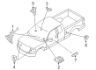
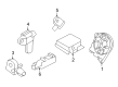
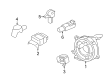
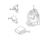
Ford Air Bag Control Module
If you own Ford and want to keep it in top shape, choosing OEM Air Bag Control Module is a smart move. They are precisely engineered and follow strict factory standards. They are made in advanced facilities that use cutting edge technology. Each part goes through thorough testing to confirm strength and safety, so you can trust it. FordPartsDeal.com gives you genuine Ford Air Bag Control Module at some of the affordable online prices without cutting quality. Every OEM Ford part includes the manufacturer's warranty, easy returns, and super-fast delivery. So why wait? Shop now and get your vehicle back to peak condition.
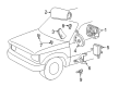
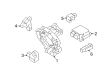
Ford Air Bag Control Module fires airbags in case crash sensors identify a real occupant danger. Ford began in 1903 and broke the rules of the industry by introducing the moving assembly line a decade later, which reduced the time spent on building a car by tenfold and allowed the average family to purchase a car. Ford continues to feel that get-it-done mentality with the EcoBoost engines that punch but drink little, as they demonstrate that there is no need to be skinny on the hood to be a muscle. Voice-controlled SYNC allows drivers to change playlists or plot a roadmap without removing their hands off the wheel, whereas Co-Pilot360 monitors lanes and brakes vehicles when drivers fall asleep. Electric vehicles such as the F-150 Lightning demonstrate that Ford has the capacity to replace the gas fumes with quiet power without sacrificing toughness. In sedans, SUVs, and workhorses, the brand pursues safer roads with intelligent hardware instead of prestigious claims. Within any modern van or pickup, the Air Bag Control Module of Ford is wired to impact sensors, has self-tests running continuously, and crash data is stored that crash investigators can later draw answers from. Upon the spiking of its accelerometers beyond a predetermined threshold, the Air Bag Control Module activates inflators within split milliseconds to protect heads and chests. The Air Bag Control Module is vehicle-agnostic and thus retains its no-nonsense logic, meaning it works equally well in families and couriers. Following a collision, the Air Bag Control Module fixes fault codes which assist software updates to enhance responsiveness in the future.
Ford Air Bag Control Module Parts and Q&A
- Q: Is the Orientation of the Air Bag Control Module Critical for the Correct Operation of the Supplemental Restraint System (SRS) on Ford Ranger?A:In order for the supplementary air bag system to operate correctly it needs proper alignment of the restraints control module (RCM). After a center tunnel collision of any SRS-equipped vehicle inspect the mountingly bracket for deformation before deciding to replace the RCM. You must replace it with a new unit if this area shows signs of damage and whether or not the air bags have engaged. Safety glasses must always be worn during SRS vehicle maintenance to protect against accidental air bag dispatch which could lead to injuries. Following car collisions the sensors require detailed inspection to assess any damage to their mounting bracket and wiring pigtail because replacement and correct positioning of defective SRS components is necessary. Memory saver devices bring risks of personal injury so they need to be avoided during all repairs. Electronic components show vulnerability to static energy since it results in module degradation. When the RCM fuse is removed while the ignition switch is ON an air bag warning lamp will turn on to indicate normal system function instead of an SRS malfunction. The vehicle must have no SRS faults or malfunctions before handing it over to the customer. Repeating the diagnostic test is required after replacing the original part when the persistent fault appears. System power should be disabled first then begin by taking out floor console parts from vehicles that utilize high-series console layouts in their design. When working on early vehicles with a utility tray owner must first take away the cup holders and then disconnect the clips before taking the utility tray off. The process for late build vehicles with utility trays includes mat removal followed by unscrewing and taking out the utility tray. The RCM needs removal after opening the electrical connector locking clip to slide it apart and disconnect the RCM by releasing its tab and then detaching the bolts. Installation requires users to first adjust the tightening torque of RCM bracket retaining bolts properly then position the RCM before bolting it into place while connecting the electrical connector and activating the locking tab. After completing the process reinstall the floor console or utility tray then activate the system power.
- Q: What precautions should be taken when servicing the air bag control module and ensuring the proper installation of the restraints control module (RCM) on Ford Mustang?A:Individuals should don protective safety glasses before servicing the air bag control module because it protects them from potential injuries caused by deployment accidents. A correct position of the restraints control module (RCM) enables proper operation for the supplemental restraint system (SRS). After evaluating collisions that harmed the center tunnel area of the vehicle it becomes necessary to check RCM mounting and bracket condition for damages before considering RCM replacement. Memory saver devices should never be used because they will increase personal injury risks. Static electricity poses a danger to electronic modules because they remain sensitive to it. Installing an appropriate RCM will help prevent the generation of diagnostic trouble codes (DTCs) that are incorrect. When the RCM fuse is removed with the ignition turned on the air bag warning lamp should illuminate because this does not suggest an SRS fault exists. Operation must be normal and no faults found in the SRS system before sending back the vehicle to customers. The diagnostic process should finish with new part installation followed by original part installation for another diagnostic test run. The procedure to remove the RCM includes depowering the system then removing the console shifter bezel followed by unscrewing the two center console top finish panel screws. Take out the six screws from the center console kick panels of driver and passenger seats to position the center instrument panel finish panel. Remove the electrical connectors before taking out the center instrument panel finish panel. Pull out the large RCM electrical connector after back-pivoting its position assurance lever while pinching the thumb tab. Remove the three nuts which secure the RCM after disconnecting its small electrical connector. Position the RCM into its place and fasten the nuts by torquing them to 12 Nm (9 lb-ft). The small RCM electrical connector needs installation when the large connector position assurance lever shows complete release from its position. When installing the large RCM electrical wires connector avoid any angle positions to prevent component damage and poor electrical connections. Secure the large RCM electrical wiring by first connecting the cable then folding the connector position assurance lever toward the RCM while making sure the thumb tab secures in place. Reinstall the six screws into the center instrument panel finish panel followed by driver and passenger kick panels. Then connect all electrical connectors and pivot the connector position assurance to engage the thumb tab. The last steps require you to install the center console top finish panel along with the two screws before installing the console shifter bezel while repowering the system.


Related Ford Parts
 Ford Ignition Coil
 Ford Relay
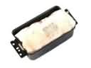 Ford Airbag
 Ford Clock Spring
 Ford Engine Control Module
 Ford Oil Pressure Gauge
 Ford PCV Valve Hose
 Ford Air Bag Sensor
 Ford Coolant Reservoir Hose
 Ford Intake Manifold Temperature Sensor
 Ford Occupant Detection Sensor
 Ford Radiator Fan Relay
Browse Ford Air Bag Control Module by Models
Ranger Bronco Mustang Explorer Focus Fusion F-150 Maverick Escape Edge Excursion Expedition Fiesta Taurus Thunderbird Flex Transit Connect Bronco Sport Explorer Sport Trac Crown Victoria Probe EcoSport Escort F-250 Aerostar Aspire C-Max Contour Country Squire E-150 Econoline Explorer Sport F-350 Five Hundred Freestar Freestyle Mustang Mach-E Police Interceptor Utility Taurus X Tempo Windstar F-350 Super Duty LTD Crown Victoria Police Interceptor Sedan E-150 E-150 Club Wagon E-150 Econoline Club Wagon E-250 E-250 Econoline E-350 Club Wagon E-350 Econoline E-350 Econoline Club Wagon E-350 Super Duty E-Transit F-150 Heritage F-150 Lightning F-250 Super Duty Police Responder Hybrid Special Service Police Sedan SSV Plug-In Hybrid Transit-150 Transit-250 Transit-350 Transit-350 HD