FordParts
My Garage
My Account
Cart
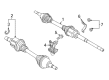
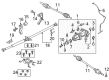
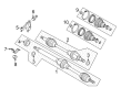
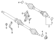
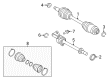
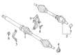
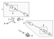
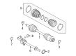
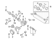
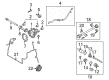
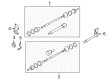
OEM Ford Axle Shaft
Car Axle Shaft- Select Vehicle by Model
- Select Vehicle by VIN
Select Vehicle by Model
orMake
Model
Year
Select Vehicle by VIN
For the most accurate results, select vehicle by your VIN (Vehicle Identification Number).
633 Axle Shafts found


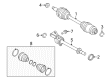
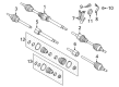
Ford Axle Assembly, Front Passenger Side Part Number: F2GZ-3B436-AF
$231.05 MSRP: $383.64You Save: $152.59 (40%)Product Specifications- Other Name: Shaft - Front Axle; CV Axle Assembly, Front Right; GSP CV Axle; Axle Shaft; CV Axle Assembly
- Position: Passenger Side


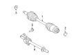
Ford Axle Assembly, Front Driver Side Part Number: F2GZ-3B437-M
$180.12 MSRP: $296.36You Save: $116.24 (40%)Ships in 1-2 Business DaysProduct Specifications- Other Name: Shaft - Front Axle; CV Axle Assembly, Front Left; Axle Shaft
- Position: Driver Side
- Replaces: F2GZ-3B437-G, F2GZ-3B437-A, TX-694, TX-757


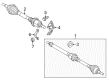
Ford Axle Assembly, Rear Part Number: F2GZ-4K138-C
$200.38 MSRP: $291.67You Save: $91.29 (32%)Ships in 1-3 Business DaysProduct Specifications- Other Name: Shaft Assembly; CV Axle Assembly, Rear; Axle Shaft
- Manufacturer Note: RH/LH
- Position: Rear
- Replaces: F2GZ-4K138-A


Ford Axle Assembly, Front Driver Side Part Number: C1BZ-3B437-C
$183.57 MSRP: $304.80You Save: $121.23 (40%)Ships in 1-2 Business DaysProduct Specifications- Other Name: Shaft - Front Axle; CV Axle Assembly, Front Left; Axle Shaft
- Position: Driver Side
- Replaces: C1BZ-3B437-A, TX-647


Ford Axle Assembly, Front Passenger Side Part Number: HG9Z-3B436-F
$219.85 MSRP: $365.05You Save: $145.20 (40%)Ships in 1 Business DayProduct Specifications- Other Name: Shaft - Front Axle; CV Axle Assembly, Front Right; Axle Shaft
- Position: Passenger Side
- Replaces: DG9Z-3B436-K, DG9Z-3B436-D, TX-620, TX-701


Ford Axle Assembly, Front Passenger Side Part Number: C1BZ-3B436-G
$312.36 MSRP: $518.65You Save: $206.29 (40%)Ships in 1-2 Business DaysProduct Specifications- Other Name: Shaft - Front Axle; CV Axle Assembly, Front Right; GSP CV Axle; Axle Shaft; CV Axle Assembly
- Position: Passenger Side
- Replaces: C1BZ-3B436-A, TX-645


Ford Axle Assembly, Front Passenger Side Part Number: 8E5Z-3A428-C
$113.72 MSRP: $190.91You Save: $77.19 (41%)Product Specifications- Other Name: Shaft - Front Axle; CV Axle Assembly, Front Right; GSP CV Axle; Axle Shaft; CV Axle Assembly
- Manufacturer Note: Includes ABS Tone Ring Not Serviced Separately
- Position: Passenger Side
- Replaces: 6E5Z-3A428-GA


Ford Axle Assembly, Front Driver Side Part Number: DP5Z-3B437-A
$171.00 MSRP: $322.15You Save: $151.15 (47%)Ships in 1-3 Business DaysProduct Specifications- Other Name: Shaft - Front Axle; CV Axle Assembly; GSP CV Axle; Axle Shaft
- Position: Driver Side


Ford Axle Assembly, Front Passenger Side Part Number: AE5Z-3A428-B
$113.64 MSRP: $186.98You Save: $73.34 (40%)Ships in 1-2 Business DaysProduct Specifications- Other Name: Shaft - Front Axle; CV Axle Assembly, Front Right; GSP CV Axle; Axle Shaft; CV Axle Assembly
- Manufacturer Note: Includes ABS Tone Ring Not Serviced Separately
- Position: Passenger Side


Ford Axle Assembly, Front Driver Side Part Number: 8E5Z-3A427-B
$101.55 MSRP: $167.09You Save: $65.54 (40%)Ships in 1-2 Business DaysProduct Specifications- Other Name: Shaft - Front Axle; CV Axle Assembly, Front Left; GSP CV Axle; Axle Shaft; CV Axle Assembly
- Manufacturer Note: Includes ABS Tone Ring Not Serviced Separately
- Position: Driver Side
- Replaces: 6E5Z-3A427-A


Ford Axle Assembly, Front Driver Side Part Number: 5M6Z-3A427-AB
$122.51 MSRP: $201.58You Save: $79.07 (40%)Ships in 1-2 Business DaysProduct Specifications- Other Name: Shaft - Front Axle; CV Axle Assembly, Front Left; GSP CV Axle; Axle Shaft; CV Axle Assembly
- Position: Driver Side
- Replaces: 5M6Z-3A427-AA


Ford Axle Assembly, Front Driver Side Part Number: AE5Z-3A427-E
$129.36 MSRP: $212.85You Save: $83.49 (40%)Ships in 1-2 Business DaysProduct Specifications- Other Name: Shaft - Front Axle; CV Axle Assembly, Front Left; GSP CV Axle; Axle Shaft; CV Axle Assembly
- Manufacturer Note: Includes ABS Tone Ring Not Serviced Separately
- Position: Driver Side
- Replaces: AE5Z-3A427-B


Ford Axle Assembly, Front Passenger Side Part Number: 6L2Z-3A428-AA
$113.82 MSRP: $187.27You Save: $73.45 (40%)Ships in 1-2 Business DaysProduct Specifications- Other Name: Shaft - Front Axle; CV Axle Assembly, Front Right; GSP CV Axle; Axle Shaft; CV Axle Assembly
- Position: Passenger Side
- Replaces: 1L2Z-3A428-AA


Ford Axle Assembly, Front Passenger Side Part Number: AL1Z-3A428-B
$129.29 MSRP: $212.73You Save: $83.44 (40%)Ships in 1-2 Business DaysProduct Specifications- Other Name: Shaft - Front Axle; CV Axle Assembly, Front Right; GSP CV Axle; Axle Shaft; CV Axle Assembly
- Position: Passenger Side
- Replaces: 7L1Z-3B436-A, AL1Z-3A428-A, TX-560

Ford Axle Assembly, Front Passenger Side Part Number: AE5Z-3A428-C
$114.47 MSRP: $188.35You Save: $73.88 (40%)Ships in 1-2 Business DaysProduct Specifications- Other Name: Shaft - Front Axle; CV Axle Assembly, Front Right; GSP CV Axle; Axle Shaft; CV Axle Assembly
- Manufacturer Note: Includes ABS Tone Ring Not Serviced Separately
- Position: Passenger Side


Ford Axle Assembly, Front Driver Side Part Number: 8S4Z-3B437-A
$108.85 MSRP: $179.11You Save: $70.26 (40%)Ships in 1-2 Business DaysProduct Specifications- Other Name: Shaft - Front Axle; CV Axle Assembly, Front Left; GSP CV Axle; Axle Shaft; CV Joint; Shaft & Joint Assembly; CV Axle Assembly
- Position: Driver Side
- Replaces: 2M5Z-3B437-CA, 5S4Z-3B437-BA, 5S4Z-3B437-AA, 6S4Z-3B437-BA, YS4Z-3B437-CB

Ford Axle Assembly, Front Passenger Side Part Number: 8E5Z-3A428-B
$151.50 MSRP: $249.27You Save: $97.77 (40%)Ships in 1-2 Business DaysProduct Specifications- Other Name: Shaft - Front Axle; CV Axle Assembly, Front Right; GSP CV Axle; Axle Shaft; CV Axle Assembly
- Manufacturer Note: Includes ABS Tone Ring Not Serviced Separately
- Position: Passenger Side
- Replaces: 6E5Z-3A428-A


Ford Axle Assembly, Front Driver Side Part Number: EV6Z-3B437-C
$159.12 MSRP: $261.82You Save: $102.70 (40%)Product Specifications- Other Name: Shaft - Front Axle; CV Axle Assembly, Front Left; GSP CV Axle; Axle Shaft; CV Axle Assembly
- Position: Driver Side
- Replaces: BV6Z-3B437-C


Ford Axle Assembly, Front Driver Side Part Number: AL1Z-3A427-B
$160.45 MSRP: $264.00You Save: $103.55 (40%)Ships in 1-2 Business DaysProduct Specifications- Other Name: Shaft - Front Axle; CV Axle Assembly, Front Left; GSP CV Axle; Axle Shaft; CV Axle Assembly
- Position: Driver Side
- Replaces: 7L1Z-3B437-A, AL1Z-3A427-A, TX-577, TX-474


Ford Axle Assembly, Front Passenger Side Part Number: FV6Z-3B436-R
$135.92 MSRP: $223.64You Save: $87.72 (40%)Product Specifications- Other Name: Shaft - Front Axle; CV Axle Assembly, Front Right; GSP CV Axle; Axle Shaft; CV Axle Assembly
- Manufacturer Note: When Replacing Half Shaft, You Must Replace The 3N324 Strap
- Position: Passenger Side
- Replaces: BV6Z-3B436-B, CV6Z-3B436-G, TX-566, TX-640
| Page 1 of 32 |Next >
1-20 of 633 Results
Ford Axle Shaft
If you own Ford and want to keep it in top shape, choosing OEM Axle Shaft is a smart move. They are precisely engineered and follow strict factory standards. They are made in advanced facilities that use cutting edge technology. Each part goes through thorough testing to confirm strength and safety, so you can trust it. FordPartsDeal.com gives you genuine Ford Axle Shaft at some of the affordable online prices without cutting quality. Every OEM Ford part includes the manufacturer's warranty, easy returns, and super-fast delivery. So why wait? Shop now and get your vehicle back to peak condition.
Ford Axle Shaft transmits the engine power to take each tire to actually move the truck forward. Ford expanded out of the original rolling assembly line under Henry to the EcoBoost turbos which stretch fuel, to SYNC voice activation that skips playlists and zero-emission pickups that have the ability to haul hard that proves progress is more than the glitzy slogans being spewed by modern drivers everywhere today. Ford takes safety far with Co-Pilot360 where automatic braking monitors traffic, the wheel is pulled by lane keeping, and a blind-spot warning system flashes a quick warning on the screen all the time the cabin remains chatty with continuous cloud updates over the years. Ford sees innovation as a normal daily business and puts new technology in the models to have a driver save on fuel, stay connected, and avoid risks instead of worrying about complicated menus or spending more money on a basic upgrade. Ford uses heat-treated steel to make the Axle Shaft in the differential housing that prevents twisting, withstands sudden hits and folds at the same time to allow the left and right wheels to rotate at different speeds on sharp turns. Axle Shaft supports weight, transfers crank output and maintains honest wheel alignment despite rising, dropping and bouncing suspension arms on ominous ruts on a daily basis. Axle Shaft is available in heavy-rig lengths as rigid, or in split half-shafts as independent, but both are successful in smoothing out the torque. Worn Axle Shaft vibrates when it is under load, shakes the cabin, and alerts the drivers well before it lets go.
Ford Axle Shaft Parts and Q&A
- Q: How to remove and install front axle shafts on a Ford Bronco?A:Loosen the wheel lug nuts, raise the front of the vehicle, and support it securely on jackstands before removing the wheels. Remove the front wheel hub(s) and the spindle assembly. For independent front suspensions, the left side axle assembly can be pulled out of the differential case, taking care as the universal joint passes through the knuckle bore. On F3.50 Monobeam front ends, both axle assemblies can be pulled out of the axle tube. For late model independent front suspensions, remove the stub axle slip joint boot clamps, slide the boot over the stub axle, and pull the drive axle from the stub axle slip joint through the knuckle bore. On early models, the right axleshaft can be slid out of the slip joint/grease seal. At this point, service the axle assembly as needed, ensuring all components are in good condition before installation. Carefully insert the left side axleshaft through the knuckle bore, engaging the axle spline with the differential side gears, and install a new RDS seal on the knuckle end with the lip facing the spindle, coating the seal face with grease. For the right side axle, insert it through the knuckle bore, engage the axle spline with the stub axle slip joint spline, and install a new RDS seal similarly. The remaining installation steps follow the reverse of removal, tightening all fasteners to the specified torque. For the right stub axle shaft on early models, remove the right side axleshaft, then the stub axle bearing retainer bolts, and pull the stub axle, seal, and bearing as an assembly from the axle housing, using a slide hammer if necessary. Service the stub axle universal joint, seal, and bearing, ensuring all components are in proper working order before installation. Install the stub axle assembly into the axle housing, engaging the differential side gear splines, and gently tap it into place until the bearing bottoms in the bore, followed by careful tapping of the seal until it seats evenly. Install the bearing retainer plate and bolts, tightening them to the specified torque, and complete the installation in reverse order. Check the lubricant level and add if necessary, then test drive the vehicle to check for leaks and proper operation. For later models with internally retained stub axle shafts, remove both axleshafts, mark the orientation of the transfer case driveshaft to the differential yoke, and remove the driveshaft. Position a drain pan under the differential, support the differential carrier with a floor jack, and remove the bolts retaining the carrier to the axle case before separating the carrier from the axle case. Rotate the stub axle shaft assembly until the open side of the axle-to-side gear snap-ring is exposed, remove the snap-ring, and pull the stub axle out of the carrier for servicing. Verify that all components are in proper working order before installing the stub axle into the right side of the carrier, engaging the splines of the side gear and installing a new snap-ring. Clean all traces of sealant from the surfaces of the carrier and axle case, apply a bead of RTV sealant around the carrier sealing surface, position the carrier on the jack, and install it in the axle case, tightening the fasteners to the specified torque. Complete the installation in reverse order, refill the case with the recommended lubricant, and check for leaks before test driving the vehicle to ensure proper operation.
- Q: What are the function and structure of the rear axle shaft assembly, and what are the common issues and diagnostic procedures associated with it on 2000-2011 Ford Ranger?A:The rear axle assembly is a hypoid semi-floating type, featuring a differential carrier made from casting with a pressed steel cover, while the axle tubes are constructed from steel, pressed and welded into the carrier. An optional Traction-Lok limited slip rear axle is available, which operates normally until one wheel loses traction, utilizing multi-disc clutch packs and a speed-sensitive engagement mechanism to lock both axleshafts together, providing equal rotational power to both wheels. Knowing the axle identification number, located on a small metal tag near one of the cover bolts, is crucial for certain operations, especially when replacing the axleshafts. Often, issues suspected in the rear axle area may actually originate elsewhere, so a thorough check is advisable before concluding a rear axle problem. Common noises associated with rear axle diagnosis include road noise, which can be mistaken for mechanical faults and remains consistent regardless of vehicle power; tire noise, which can arise from worn or under-inflated tires and remains constant during various driving conditions; and engine and transmission noise, which can mislead diagnostics as it travels along the driveline. To isolate such noises, noting the engine speed at which the noise is most pronounced and then running the engine in Neutral at the same speed can help determine if the rear axle is at fault. Overhaul and general repair of the rear axle require special tools and critical measurements, making it beyond the scope of the home mechanic, with procedures involving axleshaft removal and installation, oil seal replacement, bearing replacement, and complete unit removal for repair or replacement.


Related Ford Parts
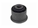 Ford Axle Pivot Bushing
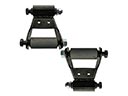 Ford Leaf Spring Shackle
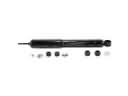 Ford Shock Absorber
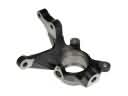 Ford Steering Knuckle
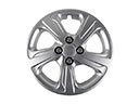 Ford Wheel Cover
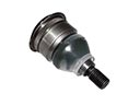 Ford Ball Joint
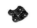 Ford Leaf Spring Plate
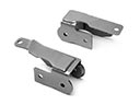 Ford Control Arm Bracket
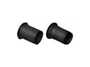 Ford Control Arm Bushing
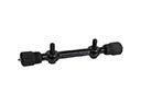 Ford Control Arm Shaft Kit
 Ford Sway Bar Bracket
 Ford Trailing Arm Bushing
Browse Ford Axle Shaft by Models
Ranger Bronco Mustang Explorer Focus Fusion F-150 Maverick Escape Edge Excursion Expedition Fiesta Taurus Thunderbird Flex Transit Connect Bronco Sport Explorer Sport Trac Crown Victoria Probe Bronco II EcoSport Escort F-250 Aerostar Aspire C-Max Contour E-150 Econoline Explorer Sport F-350 Five Hundred Freestar Freestyle Mustang Mach-E Police Interceptor Utility Taurus X Tempo Windstar F-350 Super Duty Police Interceptor Sedan E-150 E-150 Club Wagon E-150 Econoline Club Wagon E-250 E-250 Econoline E-350 Club Wagon E-350 Econoline E-350 Econoline Club Wagon E-350 Super Duty E-Transit F-150 Heritage F-150 Lightning F-250 HD F-250 Super Duty Police Responder Hybrid Special Service Police Sedan SSV Plug-In Hybrid Transit-150 Transit-250 Transit-350 Transit-350 HD