FordParts
My Garage
My Account
Cart
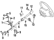
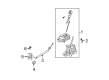
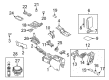
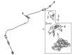
OEM Mercury Automatic Transmission Shift Levers
Automatic Transmission Shifter- Select Vehicle by Model
- Select Vehicle by VIN
Select Vehicle by Model
orMake
Model
Year
Select Vehicle by VIN
For the most accurate results, select vehicle by your VIN (Vehicle Identification Number).
53 Automatic Transmission Shift Levers found


Mercury Shift Lever Part Number: F57Z-7210-C
$106.05 MSRP: $154.37You Save: $48.32 (32%)Product Specifications- Other Name: Shaft - Gear Change; Automatic Transmission Manual Control Lever; Automatic Transmission Shift Lever; Gear Shift Assembly


Mercury Shifter Assembly Part Number: AL8Z-7210-AA
$166.25 MSRP: $242.00You Save: $75.75 (32%)Ships in 1-3 Business DaysProduct Specifications- Other Name: Lever - Gear Shift; Automatic Transmission Shift Lever; Automatic Transmission Selector Handle; Gear Shift Assembly; Shift Lever
- Replaces: 9L8Z-7210-AC, 9L8Z-7210-AA, 9L8Z-7210-AB


Mercury Shifter Assembly Part Number: AL8Z-7210-BA
$168.77 MSRP: $245.67You Save: $76.90 (32%)Ships in 1-3 Business DaysProduct Specifications- Other Name: Lever - Gear Shift; Automatic Transmission Shift Lever; Automatic Transmission Selector Handle; Gear Shift Assembly; Shift Lever
- Replaces: 9L8Z-7210-BC, 9L8Z-7210-BA, 9L8Z-7210-BB


Mercury Shifter Assembly Part Number: 8L8Z-7210-A
$180.11 MSRP: $262.17You Save: $82.06 (32%)Product Specifications- Other Name: Lever - Gear Shift; Automatic Transmission Shift Lever; Automatic Transmission Selector Handle; Gear Shift Assembly; Shift Lever
- Manufacturer Note: BLACK


Mercury Shift Lever Part Number: 7L2Z-7210-DB
$328.36 MSRP: $482.17You Save: $153.81 (32%)Ships in 1-3 Business DaysProduct Specifications- Other Name: Lever - Gear Shift; Automatic Transmission Shift Lever; Shifter Assembly; Gear Shift Assembly
- Replaces: 7L2Z-7210-DA, 6L2Z-7210-WA, 7L2Z-7210-D


Mercury Shifter Assembly Part Number: 6E5Z-7210-G
$330.85 MSRP: $485.83You Save: $154.98 (32%)Product Specifications- Other Name: Lever - Gear Shift; Automatic Transmission Shift Lever; Automatic Transmission Selector Handle; Gear Shift Assembly; Shift Lever
- Manufacturer Note: Charcoal Black
- Replaces: 6E5Z-7210-A, 6E5Z-7210-C, 6E5Z-7210-E


Mercury Shifter Assembly Part Number: 6E5Z-7210-H
$335.85 MSRP: $493.17You Save: $157.32 (32%)Ships in 1-2 Business DaysProduct Specifications- Other Name: Lever - Gear Shift; Automatic Transmission Shift Lever; Automatic Transmission Selector Handle; Gear Shift Assembly; Shift Lever
- Manufacturer Note: Charcoal Black
- Replaces: 6E5Z-7210-F
Mercury Shift Lever Part Number: 9L2Z-7210-BB
$182.06 MSRP: $265.00You Save: $82.94 (32%)Product Specifications- Other Name: Lever - Gear Shift; Automatic Transmission Shift Lever; Shifter Assembly; Gear Shift Assembly
- Replaces: 6L2Z-7210-Y, 7L2Z-7210-B, 7L2Z-7210-BA

Mercury Gear Shift Assembly Part Number: CE5Z-7210-KA
$510.64 MSRP: $749.83You Save: $239.19 (32%)Ships in 1-3 Business DaysProduct Specifications- Other Name: Lever - Gear Shift; Automatic Transmission Shift Lever; Automatic Transmission Selector Handle; Shift Housing
- Manufacturer Note: With +/- Button
- Replaces: BE5Z-7210-KA

Mercury Shift Lever Part Number: 5F1Z-7210-D
$7.13 MSRP: $9.87You Save: $2.74 (28%)Ships in 1-2 Business DaysProduct Specifications- Other Name: Housing Assembly - Gear Shift
Mercury Shifter Assembly Part Number: BL8Z-7210-CA
$99.23 MSRP: $135.03You Save: $35.80 (27%)Product Specifications- Other Name: Lever - Gear Shift; Automatic Transmission Shift Lever; Automatic Transmission Selector Handle; Shift Lever; Gear Shift Assembly


Mercury Shift Lever, Black/Charcoal Part Number: 8W1Z-7210-AC
Product Specifications- Other Name: Lever; Automatic Transmission Shift Lever; Gear Shift Assembly
- Replaces: 5W1Z-7210-AAK


Mercury Gear Shift Assembly Part Number: 5L8Z-7210-EA
$77.52 MSRP: $112.83You Save: $35.31 (32%)Product Specifications- Other Name: Housing Assembly - Gear Shift


Mercury Shift Lever Part Number: 7L5Z-7210-AA
$108.19 MSRP: $157.48You Save: $49.29 (32%)Product Specifications- Other Name: Lever - Transmission Gear Shift; Automatic/Manual Control Lever.; Gear Shift Assembly
- Replaces: 4L2Z-7210-BAA


Mercury Shift Lever Part Number: XW7Z-7210-AA
Product Specifications- Other Name: Lever - Transmission
- Replaces: F8AZ-7210-BA

Mercury Gear Shift Assembly Part Number: CE5Z-7210-GA
Product Specifications- Other Name: Lever - Gear Shift; Automatic Transmission Shift Lever; Automatic Transmission Selector Handle; Shift Housing
- Manufacturer Note: With +/- Button
- Replaces: BE5Z-7210-GA

Mercury Shift Lever, Camel Part Number: 8W1Z-7210-AB
Product Specifications- Other Name: Lever; Automatic Transmission Shift Lever; Gear Shift Assembly
- Replaces: 5W1Z-7210-AAJ

Mercury Shift Lever, Graystone Part Number: 8W1Z-7210-AA
Product Specifications- Other Name: Lever; Automatic Transmission Shift Lever; Gear Shift Assembly
- Replaces: 5W1Z-7210-AAL

Mercury Shifter Assembly Part Number: 8L8Z-7210-B
Product Specifications- Other Name: Lever - Gear Shift; Shift Lever
- Manufacturer Note: Chrome


Mercury Shift Lever Part Number: 5L2Z-7210-AA
Product Specifications- Other Name: Lever - Transmission Gear Shift; Automatic Transmission Shift Lever; Gear Shift Assembly
- Replaces: 1L2Z-7210-AD
| Page 1 of 3 |Next >
1-20 of 53 Results
Mercury Automatic Transmission Shift Levers
If you own Mercury and want to keep it in top shape, choosing OEM Automatic Transmission Shift Levers is a smart move. They are precisely engineered and follow strict factory standards. They are made in advanced facilities that use cutting edge technology. Each part goes through thorough testing to confirm strength and safety, so you can trust it. FordPartsDeal.com gives you genuine Mercury Automatic Transmission Shift Levers at some of the affordable online prices without cutting quality. Every OEM Mercury part includes the manufacturer's warranty, easy returns, and super-fast delivery. So why wait? Shop now and get your vehicle back to peak condition.
Mercury Automatic Transmission Shift Levers allow drivers to snap between gears, which maintain smooth and steady rides. Mercury began life in 1938 and soon established its own niche between fundamental transportation and high-priced luxury, selling cars that drove more smoothly but looked rougher. In honor of the fleet messenger Roman, Mercury kept showrooms busy for decades with spacious cabins, a more whispering glass, and suspensions that swallowed broken pavement without stalling steering wheels. Although models such as the Cougar and the Grand Marquis were introduced and production actually stopped in 2011, Mercury continued to pursue that balance between comfort, value, and a touch of swagger. During this time, Mercury remained committed to providing ordinary drivers with a less noisy cabin and a simple control system that they could afford. Automatic Transmission Shift Levers convert the movement of the hands of the driver into sharp gear changes by shifting through a pivoting connection that creates a distraction of friction and decreases the force required to slide between park and drive. Automatic Transmission Shift Levers also protect the well-being of the drivers since accurate detents prevent part engagement that may tear gears and heat fluid. Designed with heavy shells and pins that resist corrosion, Automatic Transmission Shift Levers shake off years of coffee spills, road salt, and temperature variations without balancing or sticking to the lever. Automatic Transmission Shift Levers fit into the original factory console without rewiring to provide reassuring control to drivers who upgrade older sedans in just one afternoon.
Mercury Automatic Transmission Shift Levers Parts and Q&A
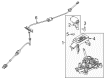
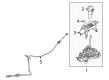
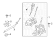
- Q: How to Service and Repair Automatic Transmission Shift Levers on the Floor on Mercury Grand Marquis?A:The service and repair of floor shifter automatic transmission shift levers require first draining the safety power supply back up to prevent air bag activation accidents before disconnecting the ground cable and waiting one minute. Additionally, disconnect all auxiliary batteries and power supplies if available. Proceed with the removal of the instrument panel finish panel followed by electrical connector disconnection. The first step involves raising the console finish panel before its removal, and afterward, you should push down on the shift handle bezel to disconnect the TC switch harness. Disassemble the shift handle by removing its two retaining screws followed by removing the part. First, disconnect the interlock cable by letting the indicator bezel rise to access the bulb before releasing the interlock cable housing clip. The shift cable requires separation at the shifter assembly while you free the shift cable housing clip. Pull the electrical connector pushpin retainer besides disconnecting the electrical connector. Disconnection of the vacuum harness from the parking brake release component is also necessary. Close by taking out the shifter while securing all nuts to 12 Nm (9 ft. lbs.) after reassembly according to the reverse process order.
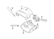
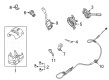
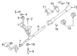
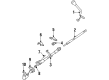
- Q: How to Service and Repair Automatic Transmission Shift Levers on the Column on Mercury Marauder?A:The first step toward servicing or repairing the column shifter automatic transmission shift levers requires the shutdown of back up power sources to stop air bag activation. The process begins by disconnecting the battery ground cable which needs waiting for at least one minute. Additionally, disable any auxiliary batteries and power supplies when present. Start the process by taking off the lower steering column opening finish panel through screw removal then position the parking brake release handle aside before undoing the screw from the panel while pulling outward to free the retaining clips. Before moving on to the next step remove the five screws that fasten both the lower steering column opening finish panel reinforcement and instrument panel reinforcement brace. To side the automatic transmission shift lever indicator cable out you must first loosen its screw and disconnect the cable from its position. To remove the ignition switch lock cylinder position the key to RUN and press the lock cylinder release pin while pulling the cylinder out. Low steering column shrouds need to be taken down through unhinging four screws before the column falls after unfastening four nuts. The next step requires separation of both Transmission Control Switch (TCS) harness from locators and gearshift lever cover from steering column after upper steering column shroud removal. The gearshift lever requires both removal of its old pin and the subsequent removal of the gearshift lever. The completion of the installation requires following the steps in reverse order with which you removed the parts.


Related Mercury Parts
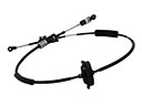 Mercury Shift Cable
 Mercury Flywheel
 Mercury Automatic Transmission Filter
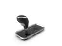 Mercury Automatic Transmission Shifter
 Mercury Clutch Disc
 Mercury Flywheel Ring Gear
 Mercury Torque Converter
 Mercury Transfer Case
 Mercury Transfer Case Seal
 Mercury Transmission Assembly
 Mercury Transmission Drain Plug
 Mercury Transmission Pan