FordParts
My Garage
My Account
Cart
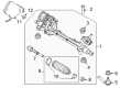
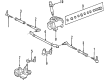
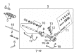
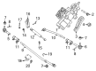
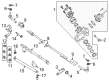
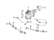
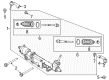
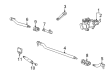
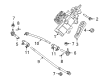
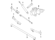
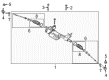
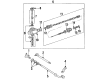
OEM Ford Rack And Pinion
Steering Gear- Select Vehicle by Model
- Select Vehicle by VIN
Select Vehicle by Model
orMake
Model
Year
Select Vehicle by VIN
For the most accurate results, select vehicle by your VIN (Vehicle Identification Number).
278 Rack And Pinions found


Ford Steering Gear Part Number: CA5Z-3504-C
$1345.05 MSRP: $2314.55You Save: $969.50 (42%)Ships in 1-2 Business DaysProduct Specifications- Other Name: Gear Assembly - Steering; Rack and Pinion Assembly; Steering Gearbox; Gear Assembly
- Replaces: AA5Z-3504-ME, AA5Z-3504-LE, AA5Z-3504-PE, AA5Z-3504-F, CA5Z-3504-CE, CA5Z-3504-A, CA5Z-3504-EE, STE-19, STE-2, STE-265, STE-273, STE-35, STE-215, STE-44


Ford Steering Gear Part Number: F75Z-3504-CBRM
$264.86 MSRP: $434.55You Save: $169.69 (40%)Ships in 1-2 Business DaysProduct Specifications- Other Name: Remanufactured Gear Assembly - Steering; Steering Gear Box; Steering Gearbox; Gear Box; Gear Assembly


Ford Steering Gear Part Number: 2R3Z-3504-BARM
$367.79 MSRP: $605.45You Save: $237.66 (40%)Ships in 1-2 Business DaysProduct Specifications- Other Name: Remanufactured Gear Assembly - Steering; Rack and Pinion Assembly; Steering Gearbox; Gear Assembly; Gear Assembly - Steering
- Replaces: XR3Z-3504-BCRM


Ford Steering Gear, Front Part Number: GU2Z-3504-A
$512.81 MSRP: $843.64You Save: $330.83 (40%)Ships in 1 Business DayProduct Specifications- Other Name: Gear Assembly - Steering; Steering Gear Box, Front; Steering Gearbox; Gear Assembly
- Position: Front
- Replaces: AC2Z-3504-A, STG-431


Ford Steering Gear Part Number: GC3Z-3504-E
$621.21 MSRP: $1023.64You Save: $402.43 (40%)Ships in 1-2 Business DaysProduct Specifications- Other Name: Gear Assembly - Steering; Steering Gear Box; Steering Gearbox; Gear Assembly
- Replaces: BC3Z-3504-B, GC3Z-3504-B, STG-427


Ford Steering Gear Part Number: HC3Z-3504-E
$775.61 MSRP: $1280.00You Save: $504.39 (40%)Ships in 1-2 Business DaysProduct Specifications- Other Name: Gear Assembly - Steering; Steering Gear Box; Steering Gearbox; Gear Assembly
- Replaces: 5C3Z-3504-BA, 7C3Z-3504-BA, 8C3Z-3504-B, HC3Z-3504-A, STG-462


Ford Steering Gear Part Number: HL3Z-3504-N
$1274.22 MSRP: $2101.82You Save: $827.60 (40%)Product Specifications- Other Name: Gear Assembly - Steering; Rack and Pinion Assembly; Steering Gearbox; Gear Assembly
- Replaces: HL3Z-3504-G

Ford Steering Gear Part Number: HL3Z-3504-L
$1311.45 MSRP: $2163.64You Save: $852.19 (40%)Ships in 1-3 Business DaysProduct Specifications- Other Name: Gear Assembly - Steering; Rack and Pinion Assembly; Steering Gearbox; Gear Assembly
- Replaces: HL3Z-3504-E


Ford Steering Gear Part Number: 2C3Z-3504-AARM
$271.38 MSRP: $443.64You Save: $172.26 (39%)Ships in 1-2 Business DaysProduct Specifications- Other Name: Remanufactured Gear Assembly - Steering; Steering Gear Box; Steering Gearbox; Gear Assembly


Ford Steering Gear Part Number: 8C2Z-3504-ARM
$281.76 MSRP: $460.00You Save: $178.24 (39%)Ships in 1 Business DayProduct Specifications- Other Name: Remanufactured Gear Assembly - Steering; Steering Gear Box; Steering Gearbox; Gear Assembly
- Replaces: 8C2Z-3504-B, 8C2Z-3504-A


Ford Steering Gear Part Number: GC3Z-3504-D
$809.55 MSRP: $1336.36You Save: $526.81 (40%)Ships in 1 Business DayProduct Specifications- Other Name: Gear Assembly - Steering; Steering Gear Box; Steering Gearbox
- Replaces: BC3Z-3504-A, GC3Z-3504-A, STG-425


Ford Steering Gear Part Number: DR3Z-3504-CE
$1011.42 MSRP: $1665.45You Save: $654.03 (40%)Product Specifications- Other Name: Gear Assembly - Steering; Rack and Pinion Assembly; Steering Gearbox; Gear Assembly
- Replaces: BR3Z-3504-ME, CR3Z-3504-CE, STE-50, STE-78

Ford Steering Gear Part Number: DR3Z-3504-BE
$1347.15 MSRP: $2163.64You Save: $816.49 (38%)Product Specifications- Other Name: Gear Assembly - Steering; Rack and Pinion Assembly; Steering Gearbox; Gear Assembly
- Replaces: BR3Z-3504-LE, CR3Z-3504-BE, STE-77, STE-49


Ford Steering Gear Part Number: F8TZ-3504-ACRM
$310.74 MSRP: $492.73You Save: $181.99 (37%)Product Specifications- Other Name: Remanufactured Gear Assembly - Steering; Steering Gear Box; Steering Gearbox; Gear Assembly; Steering Gear Assembly
- Replaces: F8TZ-3504-ABRM

Ford Steering Gear Part Number: 2R3Z-3504-CARM
$277.42 MSRP: $437.67You Save: $160.25 (37%)Product Specifications- Other Name: Remanufactured Gear Assembly - Steering; Rack and Pinion Assembly; Steering Gearbox; Gear Assembly; Gear Assembly - Steering
- Replaces: XR3Z-3504-ACRM

Ford Steering Gear Part Number: YC3Z-3504-ABRM
$302.10 MSRP: $476.36You Save: $174.26 (37%)Product Specifications- Other Name: Remanufactured Gear Assembly - Steering; Steering Gear Box; Steering Gearbox; Gear Assembly
- Replaces: YC3Z-3D517-BA


Ford Steering Gear Part Number: 7C3Z-3504-BRM
$454.19 MSRP: $720.00You Save: $265.81 (37%)Product Specifications- Other Name: Remanufactured Gear Assembly - Steering; Steering Gear Box; Steering Gearbox; Gear Assembly; Gear Assembly - Steering
- Manufacturer Note: Remanufactured
- Replaces: 7C3Z-3504-B, DC3Z-3504-B, DC3Z-3504-E, STG-452, STG-263


Ford Steering Gear Part Number: 8C3Z-3504-CRM
$490.51 MSRP: $778.18You Save: $287.67 (37%)Product Specifications- Other Name: Remanufactured Gear Assembly - Steering; Steering Gear Box; Steering Gearbox; Gear Assembly; Gear Assembly - Steering
- Manufacturer Note: Remanufactured
- Replaces: 8C3Z-3504-C, DC3Z-3504-G, DC3Z-3504-D, STG-465, STG-286, STG-454

Ford Steering Gear Part Number: 8C3Z-3504-ARM
$519.98 MSRP: $832.73You Save: $312.75 (38%)Product Specifications- Other Name: Remanufactured Gear Assembly - Steering; Steering Gear Box; Steering Gearbox; Gear Assembly; Gear Assembly - Steering
- Manufacturer Note: Remanufactured
- Replaces: 8C3Z-3504-A, DC3Z-3504-C, DC3Z-3504-F, STG-453, STG-464, STG-284


Ford Steering Gear Part Number: AL3Z-3504-ARM
$884.48 MSRP: $1421.82You Save: $537.34 (38%)Product Specifications- Other Name: Remanufactured Gear Assembly - Steering; Rack and Pinion Assembly; Steering Gearbox; Gear Assembly; Gear Assembly - Steering
- Manufacturer Note: Remanufactured
- Replaces: AL3Z-3504-A, STG-390
| Page 1 of 14 |Next >
1-20 of 278 Results
Ford Rack And Pinion
If you own Ford and want to keep it in top shape, choosing OEM Rack And Pinion is a smart move. They are precisely engineered and follow strict factory standards. They are made in advanced facilities that use cutting edge technology. Each part goes through thorough testing to confirm strength and safety, so you can trust it. FordPartsDeal.com gives you genuine Ford Rack And Pinion at some of the affordable online prices without cutting quality. Every OEM Ford part includes the manufacturer's warranty, easy returns, and super-fast delivery. So why wait? Shop now and get your vehicle back to peak condition.
Ford Rack And Pinion converts twists of the steering wheel into sharp movement of the wheels and this way each twist is accurate. Ford is a name that was established around the opening of the factory in 1903 and the moving assembly line in 1913 that cut down build time and prices for ordinary drivers. Ford is driving today with EcoBoost power that combines exhilarating speed with a stringent fuel guzzler, which saves money at the pump. Ford SYNC allows the driver to bark a song of choice or a map address and have an immediate reply in real time without fumbling. Co-Pilot360 adds automatic braking and lane alerts to ensure that the surprises remain uncommon and electric vehicles such as the 2022 F-150 Lightning are released in the market free of fumes through the tailpipe. Tech continues to develop rapidly in the brand in the interest of maintaining hands and minds focused. Rack And Pinion steering is mounted beneath the chassis in a stout mild-steel tube with a pinion gear driving a straight rack bar to convert rotation into lateral slide. Power-assisted racks have systems, which accept hydraulic muscle, thus the driver does not need to work as hard even when crawling in a parking lot. Rack And Pinion trouble is experienced in a heavy feel, squeals, or drifted car due to a worn-out seal or gears. Leaks, play, and tires of the Rack And Pinion are checked frequently, making the final Ford turn and Rack And Pinion merry.
Ford Rack And Pinion Parts and Q&A
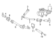
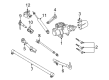
- Q: How to service and repair the front rack and pinion steering gear on Ford Expedition?A:The first step of rack and pinion repair requires hoisting the vehicle with the gear placed in neutral position. Maintain the steering column shaft in its original position throughout removal from the rack and pinion assembly because ambiguity of the clock spring can lead to damage. Therefore, check for clock spring orientation when necessary. Position the steering wheel exactly in its center position. The service starts with discarding the outer tie-rod end nuts before employing a ball joint tool separator to disconnect the tie-rod ends from wheel knuckles while attending to the tie-rod end boot. The lower cooling fan shroud tab must be freed before rotating the shroud upward. First remove the rack and pinion-to-crossmember bolts followed by disconnecting the oil drip shield along with these two bolts. Remove the steering column shaft-to-rack and pinion bolt then disconnect the shaft but prevent the shaft from rotating. The procedure to disconnect power steering lines includes removing the power steering line clamp plate bolt followed by rotating the clamp plate and discarding both O-ring seals. Unfasten the two bolts that hold rack and pinion to crossmember then proceed to remove rack and pinion discarding bolts. When installing the rack and pinion ensure the distinct seating position of the LH bushing because the RH bushing lacks locking tabs. Place the rack and pinion into position before installing two new rack and pinion-to-crossmember bolts which need to be tightened to 440 Nm (325 lb-ft). Screw in the steering column shaft before securing the bolt with a torque value of 30 Nm (22 lb-ft). Fully install O-ring seals into position before joining the steering lines through a process of clamp plate rotation followed by clamp plate bolt tightening to 23 Nm (17 lb-ft). Authenticate the oil drip shield and adjust its two bolts to 7 Nm torque level (62 lb-in). Secure the cooling fan shroud downward and connect the tie-rod ends to the wheel knuckles by tightening new nuts to 115 Nm (85 lb-ft). Complete the power steering system filling and check the front toe measurement for adjustment if required.
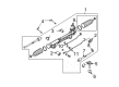
- Q: How to Service and Repair the Front Rack and Pinion Steering Gear on Ford Focus?A:Service and repair of the rack and pinion should begin by positioning the vehicle in neutral position on a hoist. Disconnect the front crossmember and the dash panel seal boot from the vehicle. The steering column coupling requires rack and pinion bolt removal before you detach it from the rack and pinion while torquing the bolt to 28 Nm (21 ft. lbs.) when reinstalling it. The next step involves removing rack and pinion bolts then the rack and pinion unit while bolting the bolts to a torque of 80 Nm (59 ft. lbs.) for reinstallation. Replacement of new O-ring seals during rack and pinion line disconnection is essential to stop power steering system failures that may result from contamination. During the process complete with the rack and pinion installation, perform power steering system fill and leak testing followed by front end alignment verification if needed.


Related Ford Parts
 Ford Power Steering Pump
 Ford Ignition Lock Cylinder
 Ford Shift Interlock Solenoid
 Ford Tie Rod
 Ford Idler Arm
 Ford Power Steering Hose
 Ford Steering Shaft
 Ford Turn Signal Switch
 Ford Power Steering Assist Motor
 Ford Steering Column Cover
 Ford Tie Rod Adjusting Sleeve
 Ford Tie Rod End
Browse Ford Rack And Pinion by Models
Ranger Bronco Mustang Explorer Focus Fusion F-150 Maverick EXP Escape Edge Excursion Expedition Fiesta Taurus Thunderbird Flex Transit Connect Bronco Sport Explorer Sport Trac Crown Victoria Bronco II EcoSport Escort F-250 Aerostar C-Max Contour Country Squire E-150 Econoline Explorer Sport F-350 Five Hundred Freestar Freestyle LTD Mustang Mach-E Police Interceptor Utility Taurus X Tempo Windstar F-350 Super Duty LTD Crown Victoria Police Interceptor Sedan E-150 E-150 Club Wagon E-150 Econoline Club Wagon E-250 E-250 Econoline E-250 Econoline Club Wagon E-350 Club Wagon E-350 Econoline E-350 Econoline Club Wagon E-350 Super Duty E-Transit F-150 Heritage F-150 Lightning F-250 HD F-250 Super Duty Police Responder Hybrid Special Service Police Sedan SSV Plug-In Hybrid Transit-150 Transit-250 Transit-350 Transit-350 HD